
Double-laser welding integrated welding head

An integrated welding head technology, applied in laser welding equipment, welding equipment, metal processing equipment, etc., can solve the problems of inconvenient cleaning or replacement, affecting the quality of welding, increasing production costs, etc., and achieve the effect of increasing the scope of use

Inactive Publication Date: 2020-03-24
JINAN G WEIKE SCI & TECH
View PDF7 Cites 0 Cited by
  • Summary
  • Abstract
  • Description
  • Claims
  • Application Information

AI Technical Summary

Problems solved by technology

[0004] In the prior art, the shielding gas supply pipeline is fixedly arranged outside the welding head, and therefore if the surface of the workpiece is irregular and has an uneven shape, the welding head of the laser welding device is likely to touch the workpiece, thereby affecting welding; The shielding gas supply pipe is set inside the welding head. After the welding head has been used for a long time, some impurities will adhere to the inner wall of the shielding gas supply pipe, which needs to be cleaned or replaced. Since the supply pipe and the welding head are integrated Therefore, it is not convenient to clean or replace it, which will affect the quality of welding. If the supply pipe is replaced, the entire welding head needs to be replaced as a whole, which will increase the production cost. Therefore, a dual laser welding integration Type welded joints are particularly important

Method used


Image

  • Double-laser welding integrated welding head
  • Double-laser welding integrated welding head
  • Double-laser welding integrated welding head

Examples


Embodiment

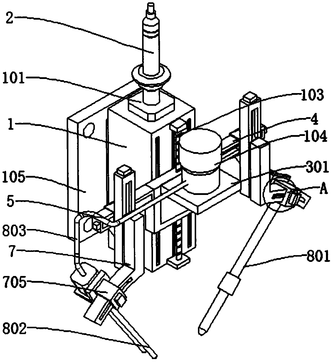
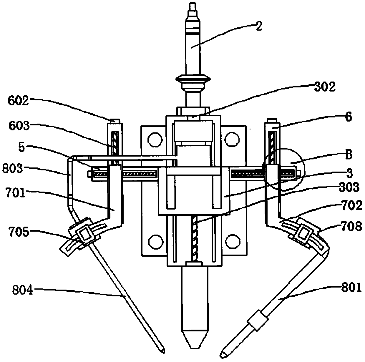
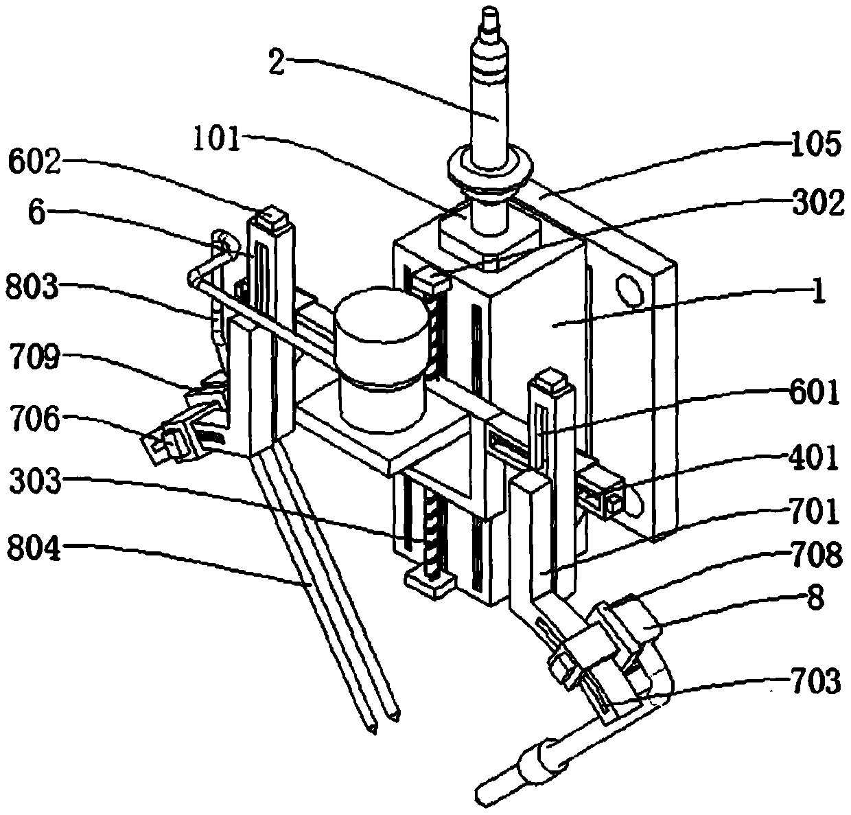
[0032] refer to Figure 1-5 , a double laser welding integrated welding head, including a base 1, a first connection seat 101 is connected to the top wall of the base 1, a laser transmitter 2 is connected to the top wall of the first connection seat 101, and the interior of the base 1 is excavated There is a channel 102 matching the laser transmitter 2, a first chute 103 is dug on the outer wall of the base 1, the first chute 103 is internally connected with a first slide 3, and the outer wall of the first slide 3 is connected with a first support plate 301, a barrel 104 is connected to the top wall of the first support plate 301, a first support frame 4 and a second support frame 5 are respectively connected to the side walls of the first slide plate 3, and a feeding assembly is movably connected to the first support frame 4, and The feeding assembly communicates with the barrel 104 , and a nozzle assembly is movably connected to the outer wall of the second support frame 5 ....


PUM


Abstract

The invention discloses a double-laser welding integrated welding head. The double-laser welding integrated welding head comprises a base; the top wall of the base is connected with a first connectingseat; the top wall of the first connecting seat is connected with a laser emitter; a first sliding groove is formed in the outer wall of the base; a first sliding plate is connected into the first sliding groove; the outer wall of the first sliding plate is connected with a first supporting plate; the top wall of the first supporting plate is connected with a material barrel; the side wall of thefirst sliding plate is connected with a first supporting frame and a second supporting frame; the first supporting frame is movably connected with a feeding assembly; the feeding assembly is communicated with the material barrel; and the outer wall of the second supporting frame is movably connected with a nozzle assembly. According to the welding head, the nozzle assembly and the feeding assembly are of a modular assembly structure, so that the welding head is convenient to disassemble, clean, repair and maintain; and the height angle of the welding head can be adjusted through the nozzle assembly and the feeding assembly, so that the welding head is convenient to machine a workpiece with an irregular surface, and therefore, the practical performance of the welding head is improved.

Description

technical field [0001] The invention relates to the technical field of welding heads, in particular to a double laser welding integrated welding head. Background technique [0002] Laser welding machine, also often called laser welding machine and laser welding machine, is a machine for laser material processing. Laser welding uses high-energy laser pulses to locally heat materials in a small area. The energy of laser radiation passes through heat conduction to The internal diffusion of the material, after the material is melted, a specific molten pool is formed to achieve the purpose of welding. [0003] When laser welding equipment is welding the workpiece, it is necessary to cover the molten pool with protective gas to prevent the molten pool from being oxidized. At present, there are two design methods for the supply pipeline of the protective gas. One is that the supply pipeline of the protective gas is separated from the welding head. , that is, the shielding gas supp...

Claims


Application Information

Patent Timeline
IPC IPC(8): B23K26/21B23K26/14B23K26/70
CPCB23K26/14B23K26/21B23K26/702
Inventor 蒋习锋赵洪路
Owner JINAN G WEIKE SCI & TECH
Learn More