Integrated mounting method for ship crane bracket and accent light mast

An installation method and crane technology are applied in the directions of ship accessories, masts, ship construction, etc., which can solve the problems that the strong light mast cannot block the rotation of the crane, the difficulty of LNG ship deck layout, and the large size of the crane bracket. Shorten the construction period, save the manufacturing cost, and reduce the effect of painting work

Active Publication Date: 2021-10-15
HUDONG ZHONGHUA SHIPBUILDINGGROUP
View PDF8 Cites 2 Cited by
  • Summary
  • Abstract
  • Description
  • Claims
  • Application Information

AI Technical Summary

Problems solved by technology

At the same time, the pipelines on the deck are dense, the crane bracket and the strong light mast are large in size, and they should be far away from each other to avoid interference, but the function requires the two to be close to each other, and there is a helicopter hovering area nearby. restrictions, this area has always been a difficult point in the layout
The current conventional method is to place the two with a certain distance apart. The strong light mast cannot block the rotation of the crane, and the light mast will be more or less blocked by the crane bracket when it is far away, which will affect the lighting effect to a certain extent.
In addition, both of them occupy a large area, and they need to pull the anti-wave anchorage cable, which occupies a larger area, which brings great difficulties to the deck layout of crowded LNG ships.

Method used


Image

  • Integrated mounting method for ship crane bracket and accent light mast
  • Integrated mounting method for ship crane bracket and accent light mast
  • Integrated mounting method for ship crane bracket and accent light mast

Examples


Embodiment Construction

[0023] The implementation of the present invention will be described by specific specific examples below, and those skilled in the art can easily understand the advantages and effects of the present invention from the content disclosed in this specification.

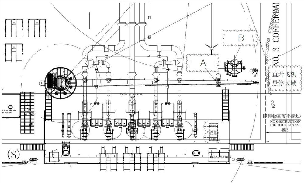
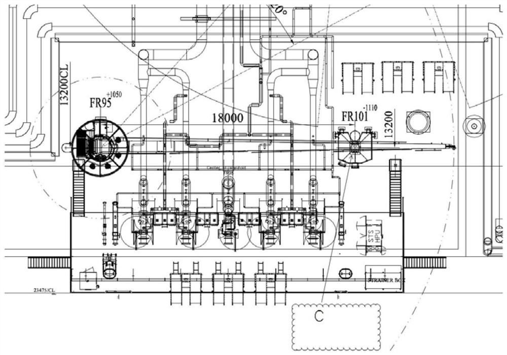
[0024] see Figure 1 to Figure 5 . It should be noted that the structures, proportions, sizes, etc. shown in the drawings attached to this specification are only used to match the content disclosed in the specification, for those who are familiar with this technology to understand and read, and are not used to limit the implementation of the present invention. Limiting conditions, so there is no technical substantive meaning, any modification of structure, change of proportional relationship or adjustment of size, without affecting the effect and purpose of the present invention, should still fall within the scope of the present invention. within the scope covered by the disclosed technical content. At the same time, t...


PUM


Abstract

The invention provides an integrated mounting structure for a ship crane bracket and an accent light mast. The ship crane bracket and accent light mast integrated installation method comprises the following steps that firstly, the installation position of a crane bracket is determined; secondly, a crane bracket and an accent light holder are manufactured; firstly, a crane bracket column body and a suspension arm supporting base installed on the top of the crane bracket column body are manufactured, the crane bracket column body and the suspension arm supporting base are welded into a whole, an operation platform is manufactured, the operation platform is arranged in the circumferential direction of the crane bracket column body, and the operation platform is located on the upper portion of the crane bracket column body. The accent light holder is installed on the outer side portion of the operation platform; thirdly, reinforcing toggle plates, an embarkation straight ladder and a straight ladder protection ring are installed; and fourthly, the strength is checked; and finite element analysis is performed on the overall strength of the crane bracket and the lamp holder platform. The accent light mast is integrated on the crane bracket, so that the arrangement space required by a deck is effectively reduced, the manufacturing cost of the accent light mast and the purchasing cost of a binding stable cable can be saved, and the manufacturing cost of a ship is saved.

Description

technical field [0001] The invention relates to the technical field of ship building, in particular to an integrated installation method of a ship crane bracket and a strong light mast. Background technique [0002] According to the requirements of the OCIMF industry standard for the transportation of liquid cargo ships, the liquid transportation operation area of ​​LNG ships is generally equipped with hose cranes for tool lifting and equipment maintenance, etc., and hose cranes are usually composed of two parts, one is the crane The main body, and the second is the bracket when the boom is stored. At the same time, according to the recommendation of the SIGTTO industry standard for the layout of the cargo delivery area of ​​​​the LNG ship, the deck of the operation area must also be equipped with a strong light mast to illuminate the night operation. Both the hose crane and the strong light mast are essential equipment, and they are arranged near the gas gathering platform...

Claims


Application Information

Patent Timeline
Patent Type & Authority Applications(China)
IPC IPC(8): B63B15/00B63B27/10B63B45/06B63B73/20
CPCB63B15/00B63B27/10B63B45/06B63B73/20
Inventor 宋锋王忠强李永福吴安戴天凌陈一强倪庆健姜志强喻义华季建洲童南汨赵志华
Owner HUDONG ZHONGHUA SHIPBUILDINGGROUP
Why Eureka
Try Eureka