Battery cell, battery applying battery cell and electronic device

A cell and battery technology, applied in non-aqueous electrolyte battery electrodes, secondary batteries, battery pack components, etc., can solve the problems of occupying the volume of the cell and reducing the energy density of the cell, and achieve the effect of improving the energy density

Inactive Publication Date: 2021-10-15
NINGDE AMPEREX TECH
View PDF0 Cites 0 Cited by
  • Summary
  • Abstract
  • Description
  • Claims
  • Application Information

AI Technical Summary

Problems solved by technology

[0003] In order to solve the problem that the empty aluminum foil at the tail of the battery occupies the volume of the battery in the prior art and reduces the energy density of the battery

Method used


Image

  • Battery cell, battery applying battery cell and electronic device
  • Battery cell, battery applying battery cell and electronic device
  • Battery cell, battery applying battery cell and electronic device

Examples


no. 1 example

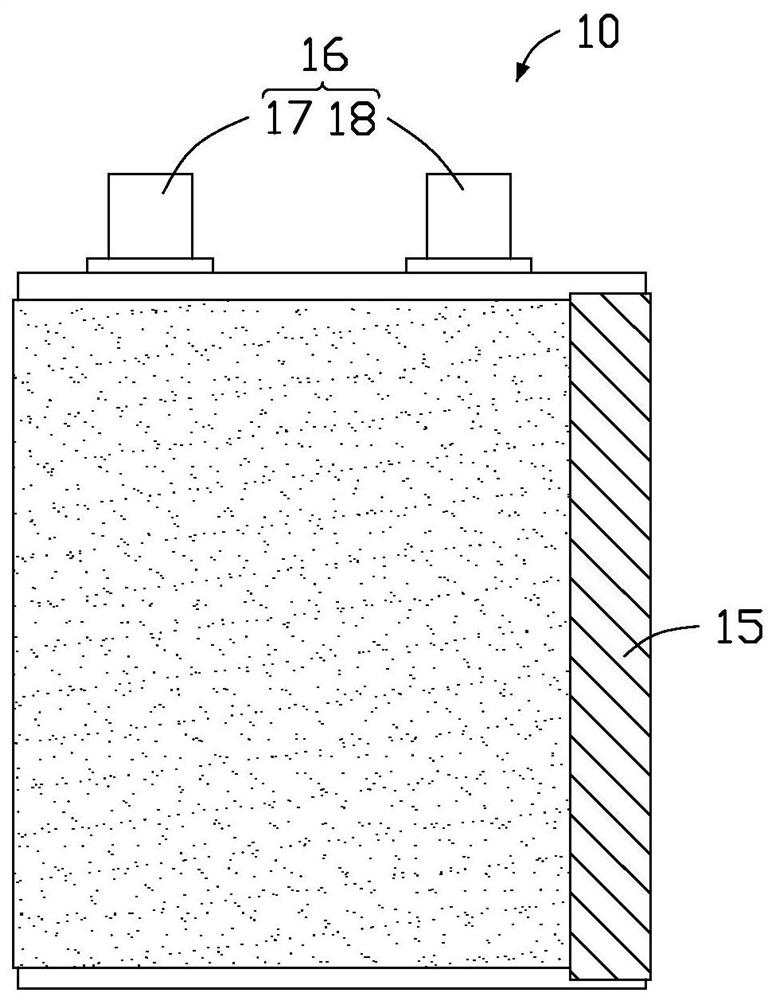
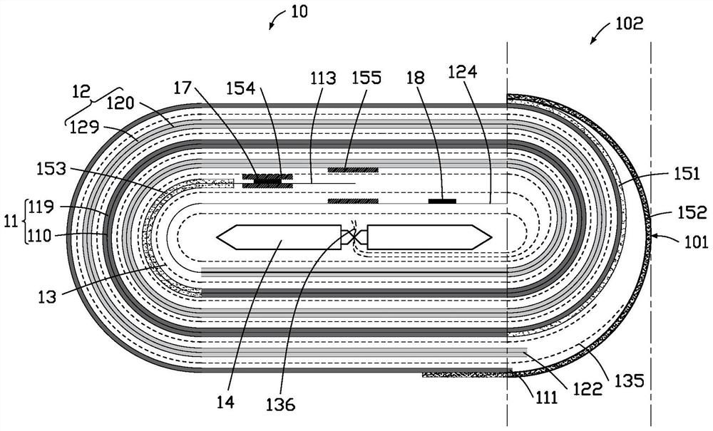
[0060] Such as figure 1 and figure 2 As shown, the first embodiment of the present application provides a battery cell 10 . The cell 10 includes a first pole piece 11, a second pole piece 12 and a separator 13, the first pole piece 11 and the second pole piece 12 are stacked at intervals, and the separator 13 is arranged on the first pole piece 11 and the second pole piece Between 12. In one embodiment, the first pole piece 11 and the second pole piece 12 can be arranged in a laminated manner. In this embodiment, the first pole piece 11 and the second pole piece 12 are coiled, and the electric core 10 also includes a rolling needle 14, the first pole piece 11, the separator 13 and the second pole piece 12 are arranged at intervals in sequence and Wrapped around the needle 14.

[0061]The first pole piece 11 includes a first current collector 110 and a first active layer 119 , and the first active layer 119 is disposed on the surface of the first current collector 110 . T...

no. 2 example

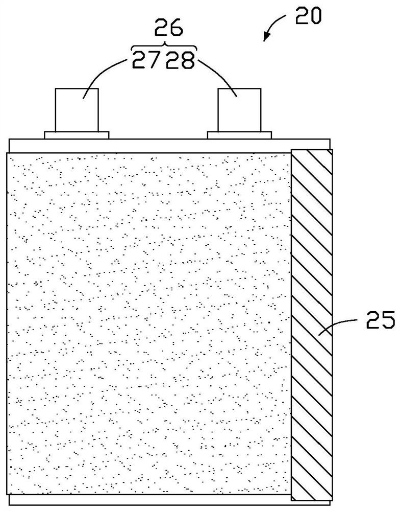
[0073] Such as image 3 and Figure 4 As shown, the second embodiment of the present application provides a battery cell 20 . The cell 20 includes a first pole piece 21, a second pole piece 22 and an isolation film 23, the first pole piece 21 and the second pole piece 22 are stacked at intervals, and the isolation film 23 is arranged on the first pole piece 21 and the second pole piece Between 22. In one embodiment, the first pole piece 21 and the second pole piece 22 can be arranged in a laminated manner. In this embodiment, the first pole piece 21 and the second pole piece 22 are coiled and arranged, and the electric core 20 also includes a coil needle 24, the first pole piece 21, the separator 23 and the second pole piece 22 are sequentially arranged at intervals and It is arranged to be wound around a winding needle 24 .

[0074] The first pole piece 21 includes a first current collector 210 and a first active layer 219 , and the first active layer 219 is disposed on t...

no. 3 example

[0086] Such as Figure 5 Shown is a schematic plan view of the battery 1 provided in the third embodiment of the present application. The battery 1 includes an electric cell 30, and the electric cell 30 may be the electric cell described in any one of the first embodiment or the second embodiment.


PUM


Abstract

The invention discloses a battery cell, which comprises a first pole piece and a second pole piece. The first pole piece comprises a first current collector and a first active layer, the first pole piece comprises a first end part, the first end part is arranged on the outer side of the battery cell, and the first active layer is arranged on the surface, located at the first end part, of the first current collector; the first pole piece and the second pole piece are wound at an interval, and the first pole piece is arranged on the outermost circle of pole piece of the battery cell; a first end face and a first cambered surface area connected with the first end face are defined, the first end part is close to the first end face and arranged in the first cambered surface area, and the first end face is a face which contains the most protruding point of the arc-shaped side face of the battery cell and extends in the thickness direction of the battery cell. The first cambered surface area is a surface of which the side surface of the battery cell is arc-shaped. The embodiment of the invention further provides a battery applying the battery cell and an electronic device.

Description

technical field [0001] The present application relates to the technical field of energy storage, and in particular to an electric cell, a battery using the electric cell, and an electronic device. Background technique [0002] In the prior art, in the general winding battery, there is a part of light aluminum foil at the tail of the outer layer pole piece of the battery core (that is, both sides of the foil are not coated with active material coating), and the light aluminum foil is finished on the surface of the battery core, so that The battery energy density is low. How to provide a new cell structure to solve the above problems is what those skilled in the art need to consider. Contents of the invention [0003] In order to solve the problem that the empty aluminum foil at the tail of the cell occupies the volume of the cell in the prior art and reduces the energy density of the cell. An embodiment of the present application provides a battery cell, including a first...

Claims


Application Information

Patent Timeline
IPC IPC(8): H01M4/13H01M10/0525H01M10/0587H01M50/533
CPCH01M10/0525H01M10/0587H01M4/13H01M50/533Y02P70/50Y02E60/10
Inventor 王攀戴志芳刘慧君龙海
Owner NINGDE AMPEREX TECH
Why Eureka
Try Eureka