Machine core for rowing machine

A rowing machine and movement technology, applied in gymnastics equipment, sports accessories, training equipment for adjusting the cardiovascular system, etc., can solve the problems of easy knotting and arrangement, easy danger, and uncontrollable resistance, so as to avoid rope out The effects of direction deviation, stable winding and winding, and consistent moving speed

Pending Publication Date: 2021-10-19
XIAMEN RENHE SPORTS EQUIP CO LTD
View PDF3 Cites 0 Cited by
  • Summary
  • Abstract
  • Description
  • Claims
  • Application Information

AI Technical Summary

Problems solved by technology

[0003] The most common damping structures of existing rowing machines are the following: wind resistance structure, magnetic resistance structure and water resistance structure. Although the above structures can achieve better exercise effects through resistance, they also have many defects. The most prominent That is, the volume is too large and the operation is complicated, as follows:
[0004] (1) Wind resistance structure, which uses the wind resistance generated by the rotation of the blades as the load on the end of the rope, but the layout of the blades not only expands the overall volume of the rowing machine, but also makes noise; the safety protection structure of the blades also greatly increases the impact on Occupation of space; more importantly, its operation structure is complicated, and the force adjustment needs to control the swing angle of the blade;
[0005] (2) The magnetic resistance structure, which uses the magnetic attraction force as the load. Although this structure is simpler than the wind resistance structure, its resistance cannot be adjusted, and the magnetic attraction parts need to be arranged precisely; High, and the layout of the magnetic attraction should not be too large, otherwise some users will find it difficult to use, if the layout of the magnetic attraction is too small, the movement effect will not be achieved, so its applicability is poor;
[0006] (3) Water resistance structure, this method is the most common, the user pulls the pull rope by holding the handle, so that the pull rope drives the blades of the rotating module to rotate, provides resistance through water resistance, and the pull rope of the rotating module is rolled up to generate elastic force , when the user no longer exerts force, the elastic force of the elastic rope drives the rotating module to rotate counterclockwise, driving the paddle and the tension rope to return to the initial position. This structure has many components, and the bucket and other components occupy a huge amount of space, and the risk factor is high. , the noise is also large;
[0007] Not only that, the direction of the pull rope on the movement of the above three methods is the same as the direction that the user pulls. Under the guidance of the rotating module in the movement, the direction of the rope is prone to deflection, causing the user's body to shake easily and muscle pulling. In addition, the movement of the existing mechanism is large in size and poor in stability. When the pull rope rotates on the rotating module, it is arbitrarily wound on the rotating module, which is easy to knot or unevenly arranged. Empty pull phenomenon, for the posture of reclining and pulling, the empty pull phenomenon is extremely dangerous

Method used


Image

  • Machine core for rowing machine
  • Machine core for rowing machine
  • Machine core for rowing machine

Examples


Embodiment Construction

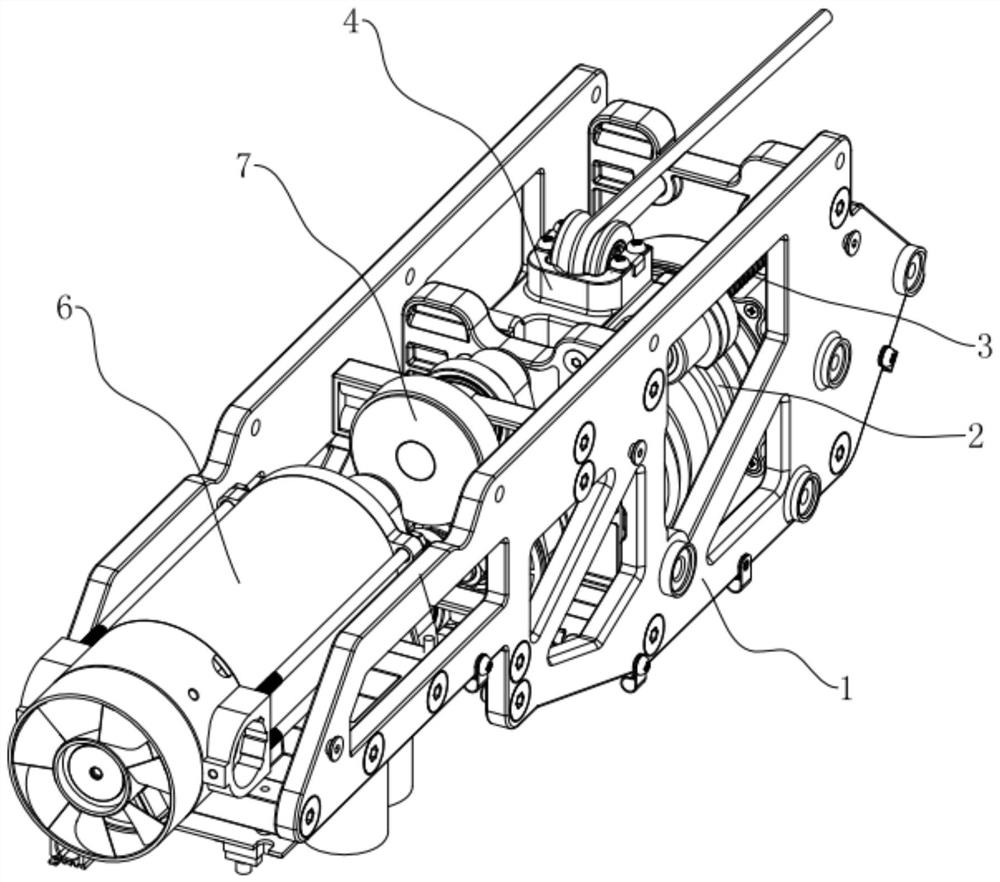
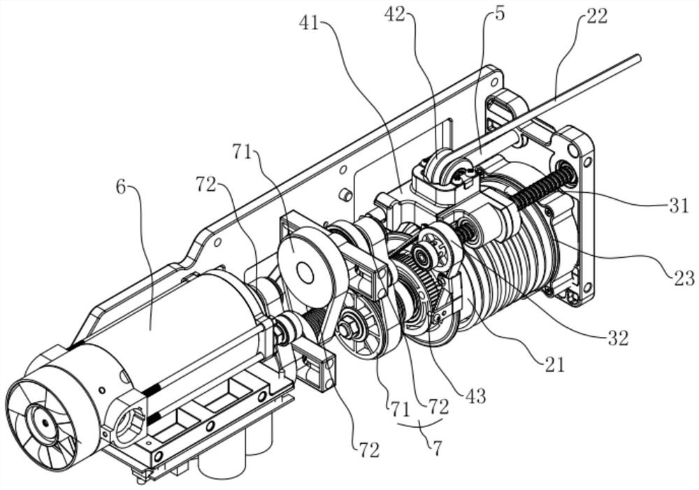
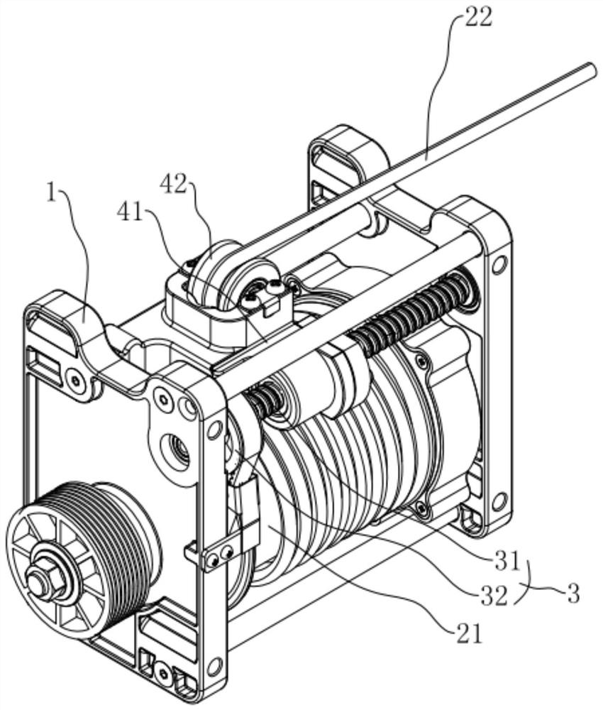
[0038] refer to Figure 1 to Figure 4 The movement for the rowing machine will be further explained.

[0039] A movement for a rowing machine, such as figure 1As shown, it includes a frame 1, a damping member 6, several groups of transmission wheel groups 7 and a winding group 2, and the damping member 6, several groups of transmission wheel groups 7 and the winding group 2 are sequentially installed on the machine along the length direction of the frame 1. on the frame 1, and the damping member 6 and the reel group 2 are respectively connected with the transmission wheel group 7 at both ends of the frame 1, so as to reduce the volume to reduce the space occupied, and make the reel group 2 rotate to drive the transmission wheel group 7 to rotate. The rotating shaft of the transmission wheel set 7 linked with the damper 6 rotates, and provides the rotation resistance of the winding group 2 through the damper 6, so that the athlete can achieve the exercise effect. In the prese...


PUM


Abstract

The invention relates to the technical field of rowing machines, and discloses a machine core for a rowing machine. The machine core comprises a rack, a coiling group, a transmission assembly and a wire guide assembly; the coiling group comprises a coiling body, a rope body and a reset piece, wherein the coiling body is rotatably arranged on the rack and arranged in the length direction of the rowing machine; the rope body is wound on the periphery of the coiling body; the reset piece is arranged in the coiling body; the wire guide assembly comprises a mounting frame, a rope body reversing piece and a linkage piece, and the mounting frame is arranged in a sliding mode relative to the rack; the rope body reversing piece is rotatably arranged on the mounting frame; the linkage piece is coaxially connected with the coiling body, the coiling body rotates to drive the linkage piece to rotate, the linkage transmission assembly drives the mounting frame to move, and the rope body reversing piece guides the rope body to move. The machine core is small in size, and the occupied space is reduced; guiding can be provided when the pull rope is output, so that deviation of the rope output direction is avoided, it is guaranteed that the pull rope is stably output, uniform winding is achieved during rotation, and the knotting condition is avoided; and the effect of improving the use stability is achieved.

Description

technical field [0001] The invention relates to the technical field of rowing machines, more specifically, it relates to a movement for rowing machines. Background technique [0002] The rowing machine is a kind of fitness equipment that has a good effect on strengthening the muscles of the legs, waist, upper limbs, chest, and back. Every time you row, the upper limbs, lower limbs, waist and abdomen, and back will complete a complete contraction and stretching in the process, which can achieve the effect of aerobic exercise for the whole body muscles. The user pulls the damping structure set on the rowing machine by pulling the rope to achieve exercise. Effect; [0003] The most common damping structures of existing rowing machines are the following: wind resistance structure, magnetic resistance structure and water resistance structure. Although the above structures can achieve better exercise effects through resistance, they also have many defects. The most prominent Tha...

Claims


Application Information

Patent Timeline
Patent Type & Authority Applications(China)
IPC IPC(8): A63B21/00A63B22/00
CPCA63B21/153A63B22/0076
Inventor 任杨杰
Owner XIAMEN RENHE SPORTS EQUIP CO LTD
Why Eureka
Try Eureka