Discontinuous rotor shrinkage fit assembling device
A shrink-fit, non-continuous technology, applied in the direction of assembly machines, metal processing equipment, manufacturing tools, etc., can solve problems such as difficulty in ensuring the coaxiality of rotor components, uncontrollable heating environment temperature, and damage to rotor shaft holes. Controllable and evenly distributed, reducing damage and ensuring uniform deformation
- Summary
- Abstract
- Description
- Claims
- Application Information
AI Technical Summary
Problems solved by technology
Method used
Image
Examples
specific Embodiment approach 1
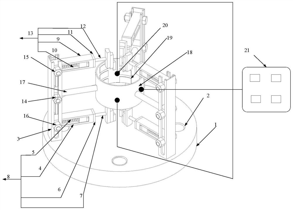
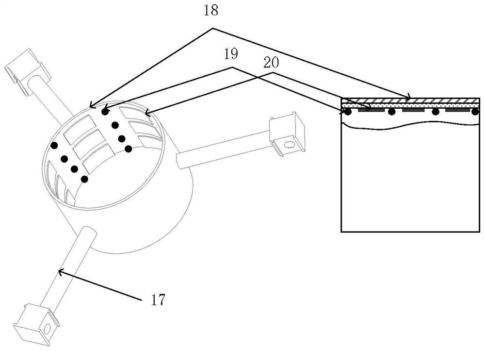
[0024] Specific implementation mode one: as Figure 1~3 As shown, the discontinuous rotor shrink-fit assembly device of this embodiment includes a base 1, a heating cylinder 18, multiple sets of thermocouples 19, multiple sets of heating tiles 20, multiple fixing brackets 3, multiple heating cylinder fixing frames 17, multiple Lower jaw disc length adjustment device 8 and multiple upper jaw disc length adjustment devices 13, fixed bracket 3, heating cylinder fixing frame 17, lower jaw disc length adjustment device 8 and upper jaw disc length adjustment device 13 are set in the same quantity, fixed bracket 3 Evenly distributed on the upper end surface of the base 1 along the circumferential direction, a slideway is processed in the fixed bracket 3 along its length direction, and one end of each heating cylinder fixing bracket 17 is connected with the middle part of a corresponding fixing bracket 3, and each heating cylinder The other end of the fixed frame 17 is connected with ...
specific Embodiment approach 2
[0025] Specific implementation mode two: as figure 1 As shown, the upper claw plate length adjustment device 13 in this embodiment includes the upper claw plate radially fixed bracket 9, the upper claw plate positioning spring 10, the upper claw plate end cover 11 and the first slider, and the upper claw plate radially fixed bracket 9 A cavity is processed inside along its length direction, and one end of the upper claw disc radially fixed bracket 9 is matched with the slideway of the fixed bracket 3 and positioned by bolts and nuts. The upper claw disc positioning spring 10 and the first slider are located on the upper claw disc In the radial fixed bracket 9 , the upper jaw disc end cover 11 covers the other end of the upper jaw disc radial fixed bracket 9 , and the connecting rod on the upper jaw disc 12 passes through the upper jaw disc end cover 11 to connect with the slider.
[0026] With such a design, the length of the upper claw plate length adjusting device 13 can be ...
specific Embodiment approach 3
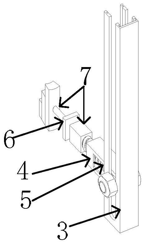
[0028] Specific implementation mode three: as figure 1 with figure 2 As shown, the lower claw plate length adjustment device 8 in this embodiment includes the lower claw plate radially fixed bracket 4, the lower claw plate positioning spring 5, the lower claw plate end cover 6 and the second slider, and the lower claw plate radially fixed bracket 4 A cavity is processed inside along its length direction, and one end of the radial fixing bracket 4 of the lower jaw plate is matched with the slideway of the fixing bracket 3 and positioned by bolts and nuts. The lower jaw plate positioning spring 5 and the second slider are located on the lower jaw plate. In the radial fixed bracket 4 , the lower jaw disc end cover 6 is covered on the other end of the lower jaw disc radial fixed bracket 4 , and the connecting rod on the lower jaw disc 7 passes through the lower jaw disc end cover 6 to connect with the slider.
[0029] With such a design, the length of the lower claw disc length ...
PUM
 Abstract
Description
Claims
Application Information
 - R&D
- Intellectual Property
- Life Sciences
- Materials
- Tech Scout
- Unparalleled Data Quality
- Higher Quality Content
- 60% Fewer Hallucinations
Browse by: Latest US Patents, China's latest patents, Technical Efficacy Thesaurus, Application Domain, Technology Topic, Popular Technical Reports.
© 2025 PatSnap. All rights reserved.Legal|Privacy policy|Modern Slavery Act Transparency Statement|Sitemap|About US| Contact US: help@patsnap.com


