A computer embroidery machine spring steel cloth clip loading and unloading device and using method thereof
A loading and unloading device and embroidery machine technology, which is applied to embroidery machines, embroidery machine mechanisms, auxiliary devices, etc., can solve the problems of time-consuming and laborious loading and unloading of spring steel cloth clips, and achieve manpower saving, stability, and continuous installation and disassembly. Effect
- Summary
- Abstract
- Description
- Claims
- Application Information
AI Technical Summary
Problems solved by technology
Method used
Image

Examples
Embodiment 1
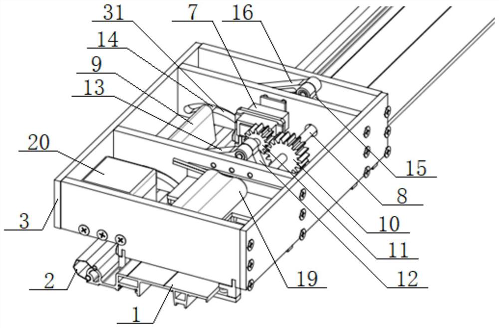
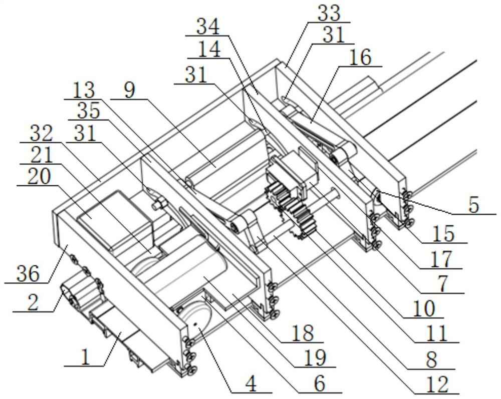
[0057] see Figure 1 to Figure 9 , a spring steel cloth clip loading and unloading device for a computerized embroidery machine, comprising a traveling mechanism and a loading and unloading mechanism; A pair of driven wheels 5 are installed on the bottom of the front end of the frame 3, and the outer peripheral surface of the driven wheels 5 is in contact with the upper surface of the frame-moving 1 of the embroidery machine. In contact with the upper surface of the moving frame 1 of the embroidery machine, the biaxial DC motor 6 is installed on the rear end of the frame 3, and the two shafts of the biaxial DC motor 6 are connected with a pair of driving wheels 4 respectively; the loading and unloading The mechanism includes a steering gear 7, a transmission shaft 8 and a loading and unloading chuck 9. The transmission shaft 8 is installed on the frame 3, and the transmission shaft 8 is equipped with a reduction gear 10, which is meshed with a reduction gear 11. The reduction...
Embodiment 2
[0065] Basic content is the same as embodiment 1, the difference is:
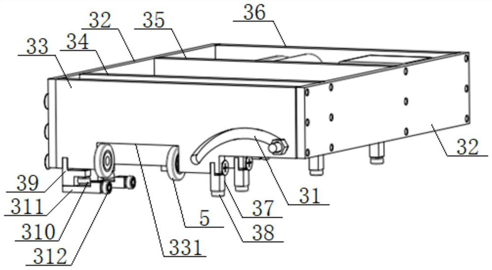
[0066] The frame 3 is a rectangular frame structure, and the frame 3 includes two vertical plates 32 and a No. 1 horizontal plate 33, a No. 1 mounting plate 34, and a No. 2 mounting plate arranged in sequence from front to back between the two vertical plates 32. 35. The No. 2 horizontal plate 36, the longitudinal plate 32 is arranged along the length direction of the moving frame 1, the No. 1 horizontal plate 33, the No. 1 mounting plate 34, the No. 2 mounting plate 35, and the No. The width direction of the frame 1 is arranged, and a pair of driving wheels 4 are located between the No. The driven wheels 5 are respectively installed on the two side walls of the inverted U-shaped groove 331, the steering gear 7 is fixed on the No. 1 mounting plate 34 through the steering gear bracket 17, and the biaxial DC motor 6 is fixed through the motor bracket 18 On the No. 2 mounting plate 35; the length of the longi...
PUM
 Abstract
Description
Claims
Application Information
 - R&D
- Intellectual Property
- Life Sciences
- Materials
- Tech Scout
- Unparalleled Data Quality
- Higher Quality Content
- 60% Fewer Hallucinations
Browse by: Latest US Patents, China's latest patents, Technical Efficacy Thesaurus, Application Domain, Technology Topic, Popular Technical Reports.
© 2025 PatSnap. All rights reserved.Legal|Privacy policy|Modern Slavery Act Transparency Statement|Sitemap|About US| Contact US: help@patsnap.com