Cooling-to-energy aerospace engine

An engine and energy technology, applied in engine components, engine cooling, machine/engine, etc., can solve the problem that the engine is difficult to greatly increase the working temperature of the nozzle in the energy chamber, it is difficult to ensure the strength of the engine structure and material, and the high-energy working fluid cannot be used. and other problems, to achieve the effect of reducing the difficulty of structure and manipulation, simple and easy storage and addition, and ensuring the strength of structure and materials

Active Publication Date: 2021-10-19
曹建峰
View PDF6 Cites 0 Cited by
  • Summary
  • Abstract
  • Description
  • Claims
  • Application Information

AI Technical Summary

Problems solved by technology

[0003] The purpose of the present invention is to provide a cooling rotary energy aerospace engine to solve the technical problems of low engine efficiency and small specific impulse; to solve the technical problems of the engine such as short working time, inability to be reused, difficult structure and control, and excessive volume ;Solve the problem that it is difficult to guarantee the engine structure and material strength; solve the technical problem that the engine uses new technology and high-energy working fluid, and the heat dissipation energy loss is serious
Solve the problem that it is difficult for the engine to greatly increase the working temperature of the energy chamber (combustion chamber) and inner nozzle, and it is impossible to use high-energy working fluid

Method used


Image

  • Cooling-to-energy aerospace engine
  • Cooling-to-energy aerospace engine
  • Cooling-to-energy aerospace engine

Examples


Embodiment Construction

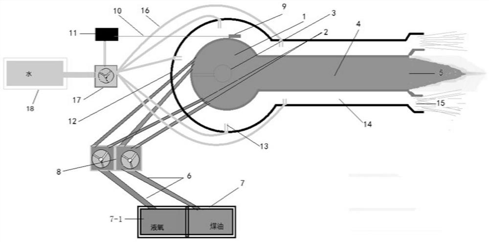
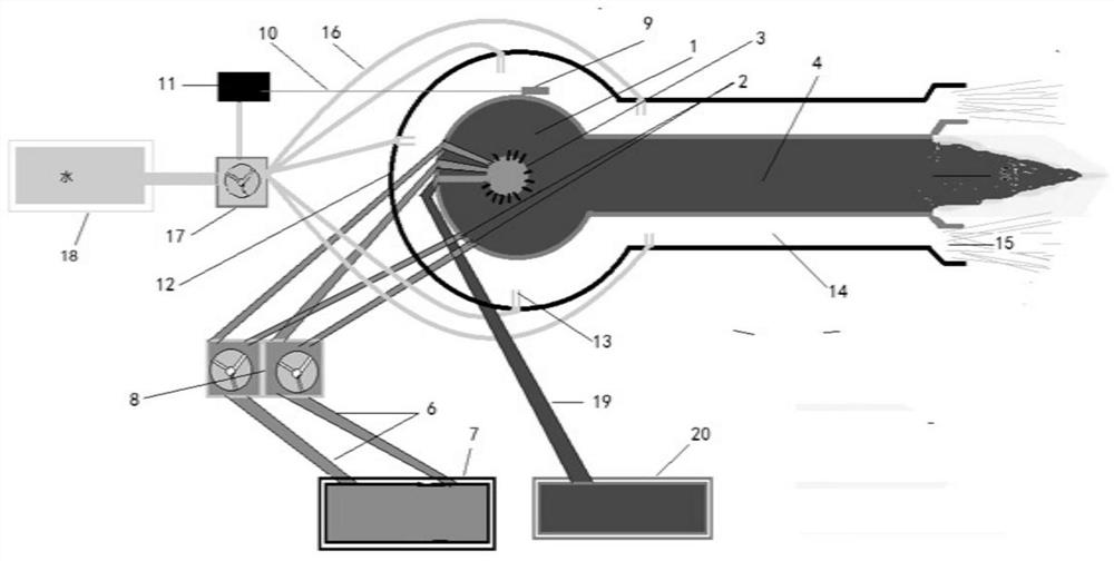
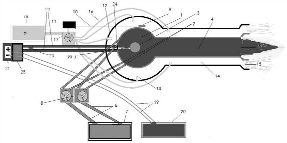
[0020] Such as figure 1 Shown: be the structural representation of embodiment 1 of the present invention, a kind of cooling transfer energy aerospace engine, its energy chamber (combustion chamber) 1, has the aperture 2 of uniform distribution, the aperture 2 other ends and working fluid conduit (propulsion) agent) 6 in communication, the working fluid conduit 6 is in communication with the working fluid compression regulator 8 and the working fluid constant temperature storage tank 7 (including the liquid oxygen storage tank 7-1); the energy chamber (combustion chamber) 1 is in communication with the inner nozzle 4, and the inner The corresponding inner nozzle 5 of nozzle pipe 4 ejects energy to do work; Ignition or energy launching device 3 is installed in the energy chamber (combustion chamber) 1, just an ignition device; the outer wall of energy chamber (combustion chamber) 1 and the inner nozzle pipe 4 The outer wall has a temperature detector 9 connected to the thermosta...


PUM


Abstract

The invention discloses a cooling-to-energy aerospace engine. The cooling-to-energy aerospace engine is characterized in that an ignition or energy emission device is arranged in an energy chamber (combustion chamber) of the cooling-to-energy aerospace engine and is used for igniting a working medium or giving energy to the working medium; small holes are distributed in the inner wall of the energy chamber and input the working medium through devices such as guide pipes; the energy chamber is connected with an inner nozzle through an inner spray pipe; temperature detectors are arranged on the outer wall of the energy chamber and the outer wall of the inner spray pipe and communicate with a temperature controller through temperature signal lines; a cooling cover sleeves the energy chamber and the inner spray pipe, and a cavity is formed between the energy chamber and the inner spray pipe to form an outer spray pipe and an outer nozzle; and small-hole spray pipes are distributed on the inner wall of the cooling cover, and one end of each small-hole spray pipe is connected with a water pressure regulator and a constant-temperature water tank through a cooling water pipe. The cooling cover, pipelines and other devices convert dissipated heat into propelling energy, the engine structure and material strength are improved, conditions are created for the engine to use the new technology and the high-energy working medium, the energy density and working temperature of the working medium in the energy chamber are greatly improved, the specific impulse is increased, long-time operation and repeated use can be achieved, and the engine is suitable for various space tasks.

Description

technical field [0001] The invention relates to an aerospace engine. Background technique [0002] At present, aerospace engines in the true sense do not exist, and the existing so-called aerospace planes have not achieved interplanetary flight, but only realized round-trip flights on the ground, in the atmosphere and in low-earth orbits outside the atmosphere, and this round-trip is useful for large-scale The aircraft is brought into high altitude, and then sent into space by its own rocket engine, or directly sent into space by a large rocket, and then sent into space by its own rocket engine for activities. At present, the most advanced aerospace engine used by various countries is trying their best to develop it. The combined power mode of turbojet engine+ramjet engine+rocket engine. Either way, the structural strength and material strength of the current engine have an upper limit, and the starting temperature needs to be controlled within a certain range. If high-ener...

Claims


Application Information

Patent Timeline
Patent Type & Authority Applications(China)
IPC IPC(8): F02K1/82F02C7/14F02C7/12F02C7/00F03H1/00
CPCF02K1/822F02C7/00F02C7/12F02C7/14F03H1/0031
Inventor 曹建峰
Owner 曹建峰
Why Eureka
Try Eureka