Oil film bearing sleeve pipe and key fixing structure

A technology of oil film bearing and bushing, applied in the field of oil film bearing, can solve the problem of high metal loss cost

Inactive Publication Date: 2004-01-21
SIEMENS IND INC
View PDF0 Cites 0 Cited by
  • Summary
  • Abstract
  • Description
  • Claims
  • Application Information

AI Technical Summary

Problems solved by technology

These metal losses are costly due to repeated heat treatment during forging and subsequent removal during machining

Method used


Image

  • Oil film bearing sleeve pipe and key fixing structure
  • Oil film bearing sleeve pipe and key fixing structure
  • Oil film bearing sleeve pipe and key fixing structure

Examples


Embodiment Construction

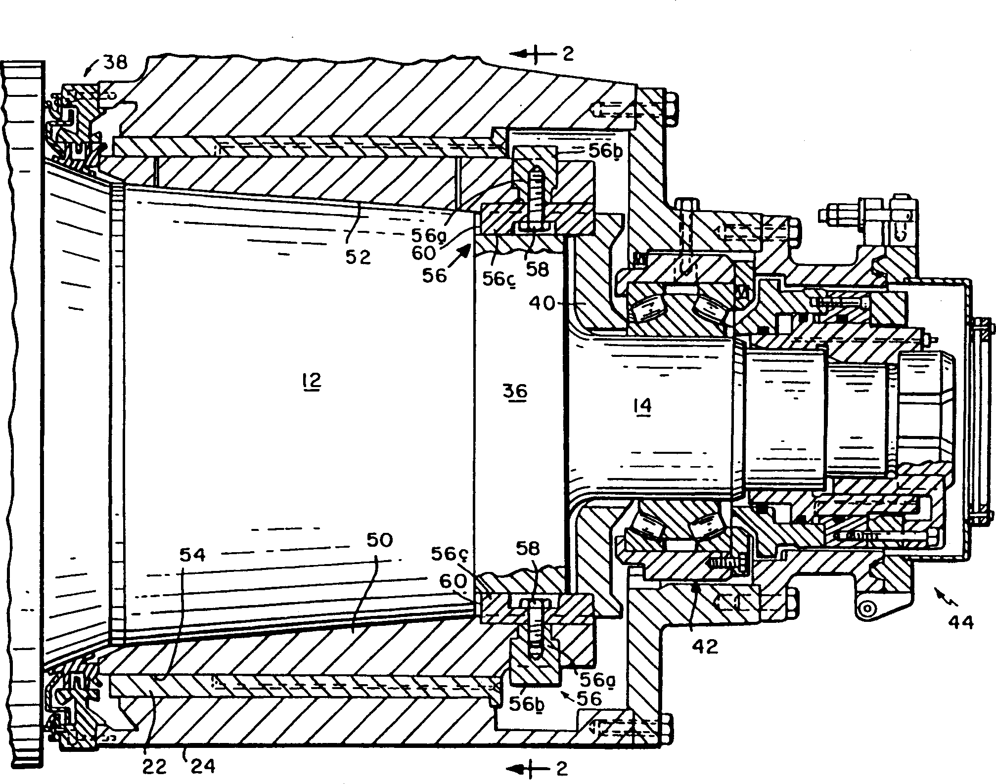
[0019] in figure 1 with 2 An oil film bearing having a redesigned key and a bond fixing structure having a preferred embodiment of the present invention, wherein the similar reference numeral has been used to identify the conventional components described above with reference to FIG. The shaft sleeve 50 of the present invention also has: a tilt inner surface 52, and a cylindrical outer surface 54, a cylindrical outer surface 54, and a cylindrical outer surface 54 to be rotated in the shaft 22 of the bearing seat 24 as a roll neck.

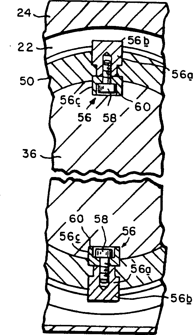
[0020] The total bond assembly shown by reference numeral 56 is used to rotatably secure the bushing to the roll neck. The two bonds are substantially T-shaped, and there is a radial segment 56a having a protruding outer portion 56b that cooperates with the shaft liner 22 during axial removal of the bearing from the roll neck. The radial section 56a extends a step well in the shaft sleeve 50 and is attached to the base 56c from a bolt 58 or other simi...


PUM


Abstract

A rolling mill oil film bearing has a sleeve with a tapered interior surface axially received on and rotatably fixed with respect to a tapered section of a roll neck. The sleeve has a cylindrical outer surface journalled for rotation within a bushing contained in a chock, with the chock, bushing and sleeve being axially removable as a unit from the roll neck. The sleeve is machined from a cylindrical forged blank which has a maximum outer diameter equal to the diameter of the sleeve's cylindrical outer surface. At least one element separate from the forged blank is secured to the sleeve. The element has a radially protruding outer portion engageable by the bushing during axial removal of the bearing unit from the roll neck.

Description

Technical field [0001] The present invention relates to an oil film bearing for rotatably supporting a roll of rolls in a roll, which is specifically referred to: Improvements in the shaft sleeve used in this bearing, and to fix this bushing. An improvement in the roll neck and its approach to the roll neck is axially removed. Background technique [0002] In a conventional form of oil film bearing shown in Fig. 7, a shaft sleeve 10 is axially housed on a inclination section 12 of a roll neck axially protruding from the roll body 16. The bushing has: an axial inner surface 18, as well as a roll neck, a roll neck, a roll neck, a cylindrical shape that is rotated in a rolling 22 in a roller bearing seat 24 Outer surface 20. One end of the bushing has a radially outwardly outwardly extending, and has a radially reached circular roller ring 28. A bonded groove 30 is processed in the roller ring 28. The key 32 can accommodate the groove 34 in the cylindrical extension 36 which is redu...

Claims


Application Information

Patent Timeline
IPC IPC(8): B02C4/28B21B27/03B21B31/07F16C13/02F16C17/02F16C35/02
CPCF16C13/02B21B2203/30B21B31/074F16C35/02F16C21/00F16C2322/12F16C2226/50B21B27/03
Inventor T·C·小渥捷克奥斯基
Owner SIEMENS IND INC
Why Eureka
Try Eureka