Metal material plastic yield strength detection device

A plastic yield and strength detection technology, applied in the direction of measuring device, analyzing material, strength characteristics, etc., can solve the problems of limited contact area, loose clamping position, inaccurate results, etc., to achieve firm clamping, avoid loosening, and ensure accurate sexual effect

Inactive Publication Date: 2021-10-19
程名丰
View PDF0 Cites 0 Cited by
  • Summary
  • Abstract
  • Description
  • Claims
  • Application Information

AI Technical Summary

Problems solved by technology

[0005] The object of the present invention is to provide a metal material plastic yield strength detection device to solve the problem that the chuck of the existing universal material testing machine proposed in the above-mentioned background technology generally adopts two inwardly shrinking splint structures to clamp the metal material, This planar splint structure is suitable for the clamping of plate-shaped metal materials; while the clamping detection

Method used


Image

  • Metal material plastic yield strength detection device
  • Metal material plastic yield strength detection device
  • Metal material plastic yield strength detection device

Examples


Embodiment example 1

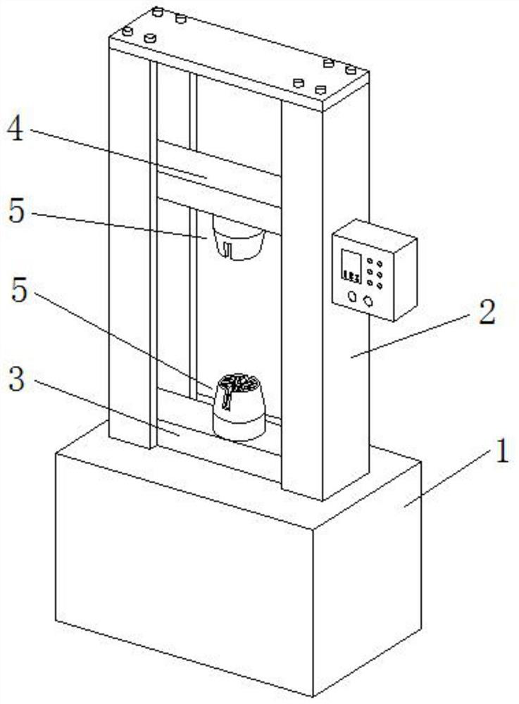
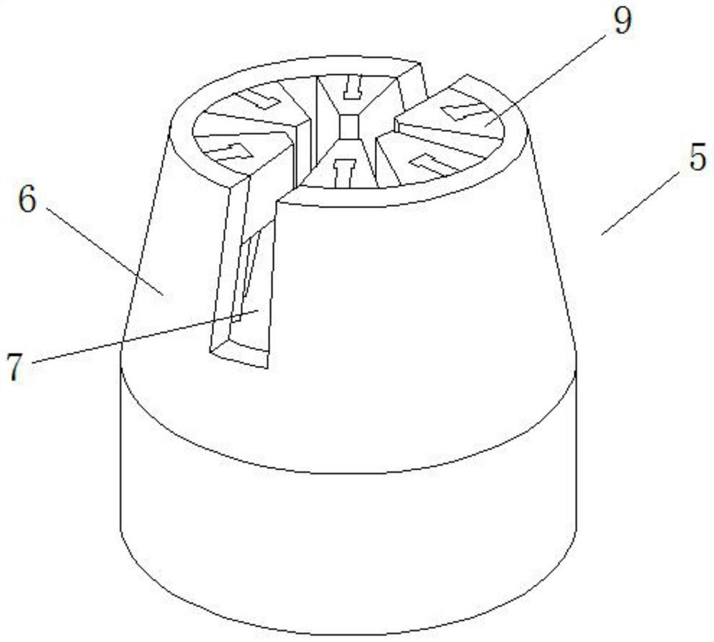
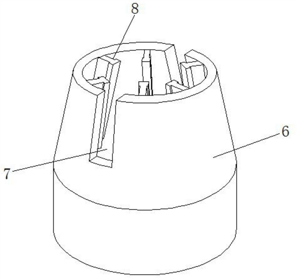
[0037] see Figure 1-4, a metal material plastic yield strength detection device, comprising a testing machine main body 1, the lower end of the bracket 2 of the testing machine main body 1 is equipped with a lower beam 3, the upper end of the bracket 2 is provided with a lifting upper beam 4, and the lower beam The middle position of the upper surface of 3 and the middle position of the lower surface of the lifting upper crossbeam 4 are fixedly installed with a chuck mechanism 5, and the chuck mechanism 5 includes an outer shell 6, and the upper side walls of the outer shell 6 are provided with The installation port 7, the upper end of the inner wall of the outer casing 6 is evenly arranged with a number of slide rails 8 on the circumference, and the sliding fan-shaped clamping blocks 9 are slidably installed on the slide rails 8, and the lower end of the inner end of the sliding fan-shaped clamping block 9 Each is provided with a fan-shaped groove 10, and a vertically arrang...

Embodiment example 2

[0044] see Figure 4 , 8 and 9, the synchronous lifting mechanism 13 includes a first support rod 16 fixed horizontally on the lower end of the inner wall of the outer casing 6 and having the same number as the sliding sector clamping block 9, and the inner ends of the first support rods 16 are all slidably installed with Vertically arranged elevating rod 17, the top of the elevating rod 17 is rotatably equipped with double-sided rollers 18 rollingly arranged inside the lower end of the sliding fan-shaped clamping block 9, and the lower end of the elevating rod 17 is provided with ring teeth 19, The lower ends of the lifting rods 17 are meshed with transmission rods 20 , and the inner parts of both ends of the transmission rods 20 are installed on the lower end of the inner wall of the outer casing 6 through the second support rods 21 .

[0045] The servo motor 26 of the synchronous lifting mechanism 13 can drive one of the transmission rods 20 to rotate through the engaged f...


PUM


Abstract

The invention discloses a metal material plastic yield strength detection device which comprises a testing machine body, a lower cross beam is installed at the lower end of a support of the testing machine body, a lifting upper cross beam is arranged at the upper end of the support, and chuck mechanisms are fixedly installed in the middle of the upper surface of the lower cross beam and the middle of the lower surface of the lifting upper cross beam correspondingly. The chuck mechanism comprises an outer shell, mounting openings are formed in the two side walls of the upper end of the outer shell, a plurality of sliding rails are circumferentially and evenly arranged at the upper end of the inner wall of the outer shell, sliding fan-shaped clamping blocks are slidably mounted on the sliding rails, fan-shaped grooves are formed in the lower ends of the inner ends of the sliding fan-shaped clamping blocks, a vertically-arranged hydraulic telescopic rod is fixedly installed in the middle of the bottom end of the interior of the outer shell, and a lifting disc is fixedly installed at the top end of the hydraulic telescopic rod. According to the chuck mechanism, plate-shaped metal materials can be conveniently clamped, meanwhile, multipoint clamping and fixing can be conducted on columnar metal materials, clamping is firm, and using is convenient.

Description

technical field [0001] The invention relates to the technical field of metal material detection, in particular to a metal material plastic yield strength detection device. Background technique [0002] Yield strength is the yield limit when the metal material yields, that is, the stress that resists micro-plastic deformation. In the prior art, a universal material testing machine is usually used to test metal materials. [0003] The chuck of the existing universal material testing machine generally adopts two inwardly shrinking splint structures to clamp metal materials. This planar splint structure is suitable for clamping plate-shaped metal materials; When holding the test, the contact area between the planar splint structure on both sides and the columnar metal material is limited, and the contact area is only the tangent position between the planar splint and the columnar metal material. Small causes loosening and sliding of the clamping position, which will lead to in...

Claims


Application Information

Patent Timeline
IPC IPC(8): G01N3/04
CPCG01N3/04G01N2203/0411G01N2203/0075
Inventor 不公告发明人
Owner 程名丰
Why Eureka
Try Eureka