
High-precision wide-range current measurement system

A technology of current measurement and large range, which is applied in the field of transient current and low-power equipment current detection, which can solve the problems of measurement range limitation, large current test error, and influence, and achieve the requirements of measurement accuracy and measurement range and improve The Effect of Measurement Accuracy and Range

Inactive Publication Date: 2021-10-19
黄森源
View PDF6 Cites 2 Cited by
  • Summary
  • Abstract
  • Description
  • Claims
  • Application Information

AI Technical Summary

Problems solved by technology

[0002] Most of the solutions currently on the market are current measurement systems that use a sampling resistor plus an amplifier. When the current passes through the sampling resistor, a voltage is generated, and the voltage of the sampling resistor is amplified by a differential amplifier. The current of the resistor, this solution is simple and easy to implement, but the disadvantages are also very obvious. The current flowing through the sampling resistor has a linear relationship with the voltage. As the current increases, the voltage difference between the two ends of the sampling resistor also increases, which affects the input of the test equipment. Voltage, different load devices have different sensitivity to input voltage. When the load device is more sensitive to voltage, the measurement range of this scheme will be greatly limited. The current measurement within the measurement range is more accurate, and the current measurement error outside the range is relatively large. Large, so the limitation is very large, so this solution is not suitable for measuring the current of equipment with large current changes

Method used


Image

  • High-precision wide-range current measurement system
  • High-precision wide-range current measurement system
  • High-precision wide-range current measurement system

Examples


Embodiment Construction

[0017] The following will clearly and completely describe the technical solutions in the embodiments of the present invention with reference to the accompanying drawings in the embodiments of the present invention. Obviously, the described embodiments are only some, not all, embodiments of the present invention. Based on the embodiments of the present invention, all other embodiments obtained by persons of ordinary skill in the art without making creative efforts belong to the protection scope of the present invention.

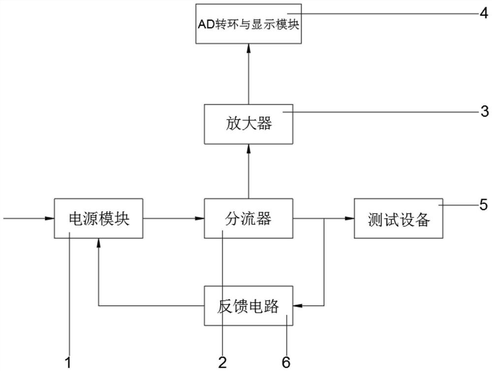
[0018] see figure 1 , a high-precision and large-range current measurement system, including a power module 1, a voltage converter is installed inside the power module 1, a signal diversion socket is installed at the output end of the amplifier 3, and the installed voltage converter can integrate the current into a relative Balanced voltage, and the signal diversion socket installed at the same time is convenient for signal transmission. The output signal of t...


PUM


Abstract

The invention relates to the technical field of low-power-consumption equipment current detection and transient current detection, and discloses a high-precision wide-range current measurement system. The system comprises a power supply module, the output end of the power supply module is in signal connection with a diverter, the output end of the top end of the diverter is electrically connected with an amplifier, and the output end of the amplifier is electrically connected with an AD rotating ring and a display module. According to the high-precision wide-range current measurement system, current enters the diverter, the diverter guides the entering current to enter different gain circuits, high-precision measurement of a low current value and wide-range measurement of a large current value are achieved, the requirements for measurement precision and measurement range are achieved; then the current enters the amplifier after passing through the diverter, the amplifier amplifies the current output by the diverter to improve the measurement precision and range, and then the AD rotating ring and the display module are mainly used for carrying out digital-to-analog conversion and display on the signal output by the amplifier.

Description

technical field [0001] The invention relates to the technical field of low power consumption equipment current detection and transient current, in particular to a high-precision and large-range current measurement system. Background technique [0002] Most of the solutions currently on the market are current measurement systems that use a sampling resistor plus an amplifier. When the current passes through the sampling resistor, a voltage is generated, and the voltage of the sampling resistor is amplified by a differential amplifier. The current of the resistor, this solution is simple and easy to implement, but the disadvantages are also very obvious. The current flowing through the sampling resistor has a linear relationship with the voltage. As the current increases, the voltage difference between the two ends of the sampling resistor also increases, which affects the input of the test equipment. Voltage, different load devices have different sensitivity to input voltage....

Claims


Application Information

Patent Timeline
Patent Type & Authority Applications(China)
IPC IPC(8): G01R19/25
CPCG01R19/25
Inventor 黄森源
Owner 黄森源
Learn More