Control method for dynamic falling of loop of hot continuous rolling mill

A technology of hot tandem rolling mill and control method, applied in the direction of tension/pressure control, etc., can solve the problems of the negative impact of stable rolling of the rear stand, the inability to form an effective transition at the tail of the strip, and the damage of the looper roll surface, so as to reduce the Maintenance repair and spare parts costs, avoidance of scratch defects on the lower surface, the effect of prolonging the service life

Pending Publication Date: 2021-10-22
BAOSHAN IRON & STEEL CO LTD
View PDF5 Cites 1 Cited by
  • Summary
  • Abstract
  • Description
  • Claims
  • Application Information

AI Technical Summary

Problems solved by technology

However, when the upstream frame throws steel, the overall tension of the strip decreases, and the magnitude of the decrease increases with the increase of the steel throwing frame. The increase in the speed at the rear of the frame further aggravates the loss of tension, causing the strip steel to flick, unfinished, or even deviate from the pile of steel in the rear frame.
The existing looper control is often unable to fully compensate for the loss of tension caused by various reasons, resulting in the drifting, unfinished, or even deviation of the steel strip in the rear rack;
[0010] 2) The tail of the strip steel is narrowed
When the tension between the racks is too large due to abnormal factors, the main control speed intervenes to adjust the speed increase of the front rack, resulting in a rapid increase in the metal second flow of the front rack, and the rapid adjustment of the looper causes the angle to be too low after the overshoot. It will cause the tail of the strip to fail to form an effective transition, resulting in the phenomenon of the tail flicking after the front rack throws steel, which will have a serious negative impact on the stable rolling of the rear rack, and easily cause the tail to be broken;
[0012] 4) Scratches on the lower surface of the strip steel tail
Severe looper angle control at the tail of the strip will cause scratches on the lower surface of the strip;
[0013] 5) Roller surface damage and abnormal wear of the looper roller
Tail tension caused the tail to fold into the rear frame, causing scrap in the rear frame

Method used


Image

  • Control method for dynamic falling of loop of hot continuous rolling mill
  • Control method for dynamic falling of loop of hot continuous rolling mill
  • Control method for dynamic falling of loop of hot continuous rolling mill

Examples


Embodiment

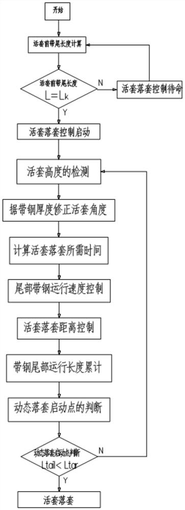
[0099] When the rolling is close to the tail of the strip, the distance traveled by the tail is judged, that is, the distance L traveled by the tail of the strip tail tar , where (L tail : the distance traveled by the tail of the strip; L tar : the walking distance of the strip during the looper falling) the looper enters the original falling control; carry out the small looper control, the small looper angle of the three hot rolling is set to 14 degrees, the following table 2 is that the looper carries out the small looper Timing of looper control.

[0100] Table 2

[0101]

[0102] L=Lk (the length of the tail before the finishing rolling loop, where: k is the looper from F1 to F6)

[0103] The 2# looper control data was sampled. This group of data reflects the action of the looper under normal circumstances, and the control is relatively good. L2 sets the angle to 20 degrees, and sets the tension to 5.6MPa. The angle and tension of the looper are relatively normal ...


PUM


Abstract

The invention discloses a control method for dynamic falling of a loop of a hot continuous rolling mill. The control method comprises the following steps: 1, calculating the tail length of strip steel in front of the loop; step 2, performing secondary correction on the height of the loop, controlling matrix time, and tracking the accumulated length of strip steel operation; and 3, judging a dynamic loop falling starting point, and carrying out loop falling after conditions are met. According to the method, different loop heights are combined, loop dynamic loop falling control is adopted, and the loop stability of the strip steel in the steel throwing process is greatly improved through the strip steel operation accumulated length control technology, the loop height secondary correction technology and the matrix time control technology.

Description

technical field [0001] The invention relates to a control technology for looper drop-off of a hot continuous rolling mill, and more specifically relates to a dynamic drop-off control method of a hot continuous rolling mill looper. Background technique [0002] Loopers are installed between the finishing mills of today's hot continuous rolling production line, and its purpose is to ensure that the strip steel between every two rolling mills has a specific tension. The looper uses an extra tension to prevent the narrowing of the strip. Excessive tension will cause the strip to break. This situation occurs when the flow of the rear rack is greater than that of the front rack, that is, the speed of the rear rack Greater than the front frame, when the flow of the rear frame is smaller than that of the front frame, the strip will be folded, and the looper will be lifted at this time, otherwise it will cause abnormal belt threading. [0003] In this way, it is necessary to install...

Claims


Application Information

Patent Timeline
Patent Type & Authority Applications(China)
IPC IPC(8): B21B37/50
CPCB21B37/50
Inventor 郁华军王军
Owner BAOSHAN IRON & STEEL CO LTD
Why Eureka
Try Eureka