
A kind of 7-shaped hole processing method

A hole processing method and glyph technology, which are used in perforating tools, metal processing equipment, manufacturing tools, etc., can solve the problems of long processing time, high labor cost, poor punching accuracy of parts, etc., and achieve high positioning accuracy and high production efficiency. , The effect of high punching precision

Active Publication Date: 2022-07-19
DONGFENG LIUZHOU MOTOR
View PDF39 Cites 0 Cited by
  • Summary
  • Abstract
  • Description
  • Claims
  • Application Information

AI Technical Summary

Problems solved by technology

[0002] Punching is a stamping process that uses a die to separate part of the material or process part from another part of the material, process part or waste. The burr of the punched part is inevitable, and the height of the burr generally does not exceed 0.2-0.3mm, otherwise the punching The parts need to be polished and removed before use. However, in the existing punching method of the 7-shaped hole, the first punching line is in the plane position, and the second punching line is at the intersection position of the first punching line. In the plane position, the angle between the tangent line at any point of the boundary line between the first punching line and the second punching line and the direction of the second punching process is small, that is, the punching angle is small, only an acute angle of 4-6° , resulting in large burrs in the second punching, and subsequent manual grinding is required. The labor cost is high, the processing time is long, and more iron filings are generated, which are easy to crush the surface of the part. In addition, the punching can only pass through the surface Positioning makes it easy to misalign between the two processes of the 7-shaped, resulting in the inability to cut off waste and poor punching accuracy of parts

Method used


Image

  • A kind of 7-shaped hole processing method
  • A kind of 7-shaped hole processing method

Examples


Embodiment Construction

[0021] The specific embodiments of the present invention will be described in further detail below with reference to the accompanying drawings and embodiments. The following examples are intended to illustrate the present invention, but not to limit the scope of the present invention.

[0022] In the description of the present invention, it should be understood that the terms "center", "longitudinal", "horizontal", "upper", "lower", "front", "rear", "left", "lateral", The orientation or positional relationship indicated by "right", "vertical", "horizontal", "top", "bottom", "inside", "outside", etc. is based on the orientation or positional relationship shown in the drawings, and is only for the convenience of description The present invention and simplified description do not indicate or imply that the device or element referred to must have a particular orientation, be constructed and operate in a particular orientation, and therefore should not be construed as limiting the ...


PUM

PropertyMeasurementUnit
radiusaaaaaaaaaa

Abstract

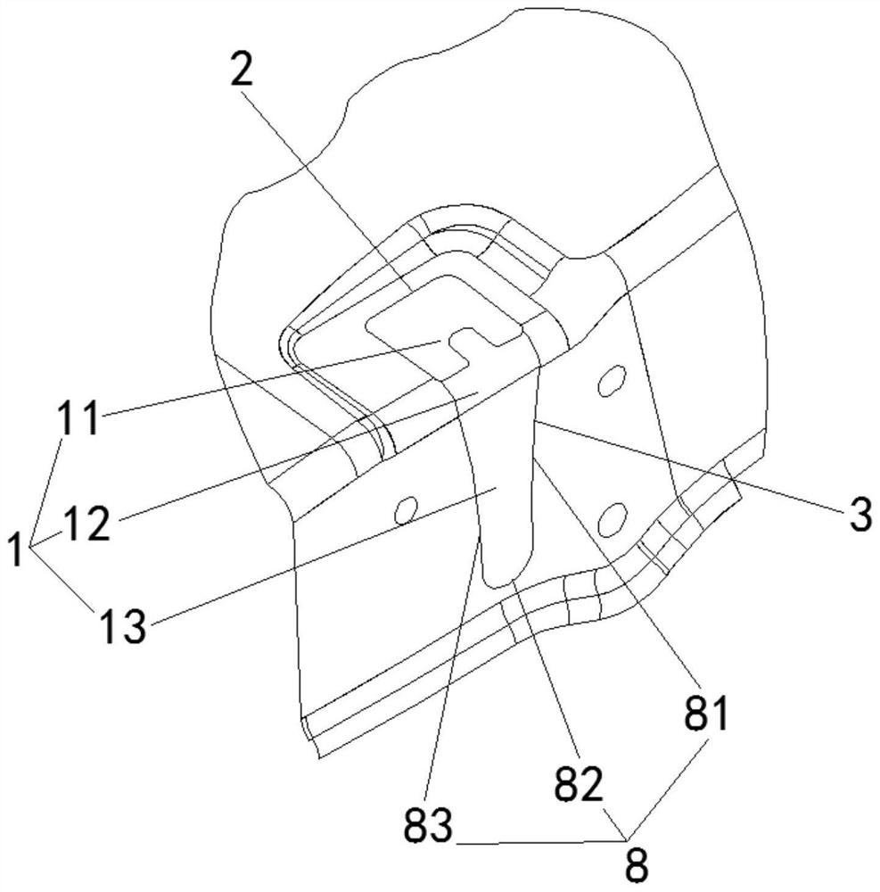
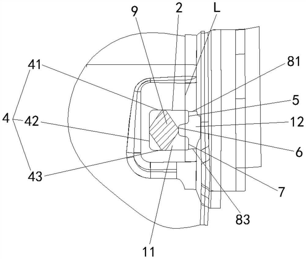
The invention relates to the technical field of punching, and discloses a figure-7 hole processing method, comprising the following steps: S1, the first contour line is the border line of the horizontal part, and the second contour line and the fourth contour line are both located in the bending part , the third contour line is located in the horizontal part, the second contour line, the third contour line and the fourth contour line are connected in the shape of a few characters, the fifth contour line is the edge line of the vertical part, the second contour line, the third contour line The line and the fourth contour line are the junction line of the first punching line and the second punching line; S2, place the part in the mold, and carry out the first punching according to the first punching line, and the first punching direction is vertical On the plane where the horizontal part is located; S3, install a positioning pin in the area that has been punched in step S2, and then perform a second punching according to the second punching line, and the direction of the second punching is perpendicular to the plane where the vertical part is located, complete 7-shaped hole processing. The invention has the advantages of high punching die strength, small burr, high production efficiency, high positioning precision and high punching precision.

Description

technical field [0001] The invention relates to the technical field of punching, in particular to a method for processing a 7-shaped hole. Background technique [0002] Blanking is a stamping process that uses a die to separate some materials or process parts from another part of materials, process parts or waste. The burr of the blanking parts is inevitable, and the height of the burr is generally not more than 0.2-0.3mm, otherwise the punching The burrs need to be removed before the parts are used, but the existing punching method of the 7-shaped hole, the first punching line is in the plane position, and the second punching line and the first punching are at the current position of the knife In the plane position, the angle between the tangent at any point of the boundary line between the first punching line and the second punching line and the direction of the second punching process is small, that is, the punching angle is small, only an acute angle of 4-6° , resulting...

Claims


Application Information

Patent Timeline
Patent Type & Authority Patents(China)
IPC IPC(8): B21D28/34B21D28/04B21D28/24
CPCB21D28/34B21D28/04B21D28/243
Inventor 贾庚凤廖勇冼世艺石盛强姜慧丽祁富钧覃存君徐蓉吴秀桃
Owner DONGFENG LIUZHOU MOTOR
Learn More