
Automatic plasma cutting device capable of realizing high-quality cutting and convenient to operate

An automatic cutting device and plasma technology, applied in plasma welding equipment, welding equipment, metal processing equipment, etc., can solve the problems of irregular cutting surface, excessive auxiliary time, disproportionate cost and return, and achieve low manpower and financial costs , The effect of neat cutting surface

Pending Publication Date: 2021-10-22
CHENGDU AEROSPACE FENGHUO PRECISION ELECTROMECHANICAL
View PDF0 Cites 0 Cited by
  • Summary
  • Abstract
  • Description
  • Claims
  • Application Information

AI Technical Summary

Problems solved by technology

[0005] When using manual cutting, the general operation method is to first mark the material to be cut by scribing, and cut along the scribing line when cutting. The cutting speed and cutting accuracy are closely related to the operator's experience, which is easy to cause the cutting surface Irregularity, especially straightness and roundness cannot be well guaranteed
[0006] When using large-scale two-axis and three-axis equipment for cutting, first use the computer to program the cutting trajectory and parameters, and then perform corresponding cutting after debugging, which puts forward higher skill requirements for the operator and requires programming, etc. Therefore, higher costs are required in terms of manpower and financial resources. For applications that only require simple cutting, more auxiliary time will be generated and the cost is not proportional to the return, so it is not suitable for popularization and application.

Method used


Image

  • Automatic plasma cutting device capable of realizing high-quality cutting and convenient to operate
  • Automatic plasma cutting device capable of realizing high-quality cutting and convenient to operate
  • Automatic plasma cutting device capable of realizing high-quality cutting and convenient to operate

Examples


Embodiment Construction

[0025] The present invention will be further described below in conjunction with accompanying drawing:

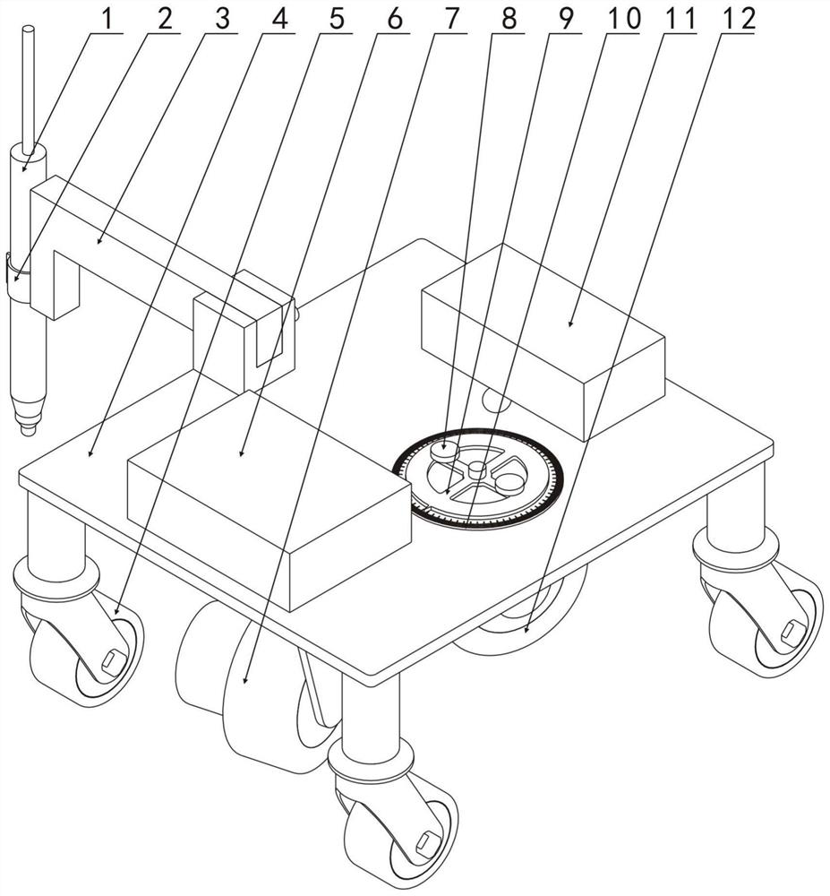
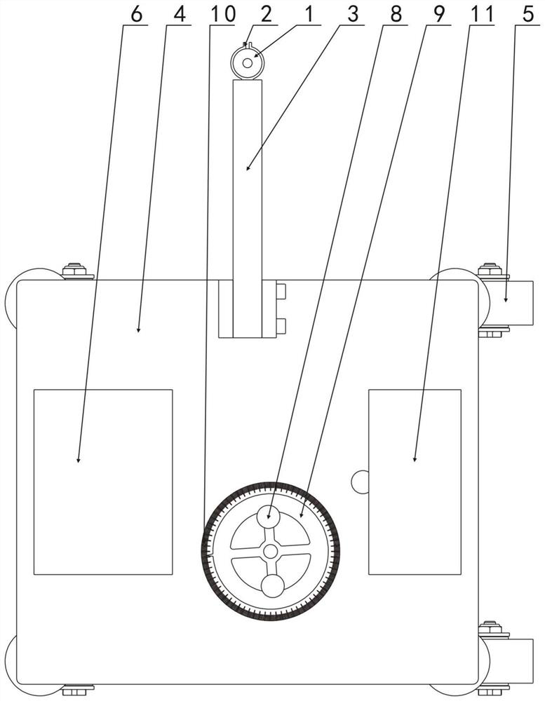
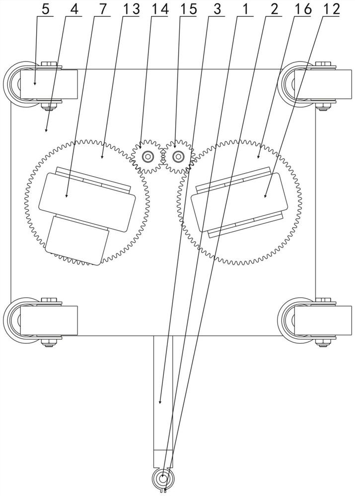
[0026] Such as Figure 1-Figure 4 As shown, the plasma automatic cutting device that can realize high-quality cutting and is easy to operate according to the present invention includes a plasma cutting torch 1, a base 4, a universal roller 5, a driving steering gear 13, a driven steering gear 16, a driving roller 7, Driven roller 12, adjustment gear 15 and transmission gear 14, a plurality of universal rollers 5 are installed below the base 4, and horizontal driving steering gear 13 and horizontal driven steering gear 16 are respectively installed below the base 4 and Can rotate, the driving roller 7 that has driving motor (unmarked among the figure) is fixedly installed below driving steering gear 13, the driven roller 12 that does not have driving motor is fixedly installing below driven steering gear 16, driving roller 7, The following of the driven roller 12 and a plur...


PUM


Abstract

The invention discloses an automatic plasma cutting device capable of realizing high-quality cutting and convenient to operate. The automatic plasma cutting device comprises a plasma cutting gun, a base, universal rollers, a driving steering gear, a driven steering gear, a driving roller, a driven roller, an adjusting gear and a transmission gear, wherein a plurality of universal rollers, the driving steering gear and the driven steering gear are respectively mounted below the base, the driving roller is fixedly mounted below the driving steering gear, the driven roller is fixedly mounted below the driven steering gear, the adjusting gear and the transmission gear which are connected in a meshed mode are mounted below the base and located between the driving steering gear and the driven steering gear, and the adjusting gear and the transmission gear are connected with the driving steering gear or the driven steering gear in a meshed mode. Accurate linear, circular, arc-shaped and other cutting can be achieved, the cutting face is neat, the high-quality plasma cutting task is completed with low manpower and financial cost, and the automatic plasma cutting device is suitable for application and popularization.

Description

technical field [0001] The invention relates to a plasma automatic cutting device, in particular to a plasma automatic cutting device which can realize high-quality cutting and is easy to operate. Background technique [0002] Plasma cutting technology is a cutting technology that uses high-energy-density plasma arc and high-speed plasma flow to blow away the molten metal from the cutting edge, thereby forming a continuous gap. This cutting technology has high energy density, small cutting deformation, No need to preheat before cutting, wide range of cutting metals, etc., can cut stainless steel, aluminum, copper, copper and ordinary carbon steel and other non-ferrous metals. At the same time, the plasma cutting industry has obvious development advantages: compared with gas flame cutting, plasma cutting is faster, more efficient, and better in quality; compared with laser cutting, plasma cutting has obvious advantages in cost. [0003] At present, the method of plasma cutti...

Claims


Application Information

Patent Timeline
Patent Type & Authority Applications(China)
IPC IPC(8): B23K10/00
CPCB23K10/00
Inventor 苟渝路苟大利肖卫洪卢圆圆
Owner CHENGDU AEROSPACE FENGHUO PRECISION ELECTROMECHANICAL
Learn More