
Capacitance sensing equipment and laser cutting head

A capacitive sensing, capacitive sensor technology, applied in welding equipment, laser welding equipment, metal processing equipment, etc., can solve problems such as damage to capacitive sensing equipment

Pending Publication Date: 2021-10-22
HANS LASER TECH IND GRP CO LTD +1
View PDF6 Cites 0 Cited by
  • Summary
  • Abstract
  • Description
  • Claims
  • Application Information

AI Technical Summary

Problems solved by technology

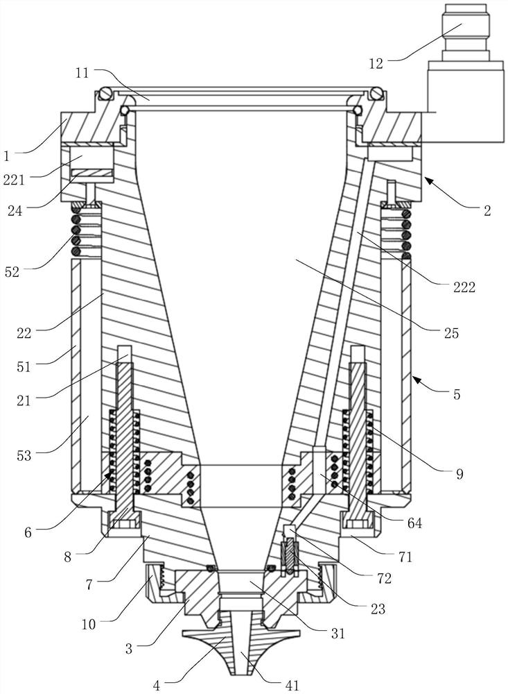
[0004] The invention solves the technical problems of damage to the capacitive sensing device caused by the inability to stop the movement in time when the existing capacitive sensing device collides with the workpiece to be cut, and provides a capacitive sensing device and a laser cutting head

Method used


Image

  • Capacitance sensing equipment and laser cutting head
  • Capacitance sensing equipment and laser cutting head
  • Capacitance sensing equipment and laser cutting head

Examples


Embodiment Construction

[0026] In order to make the technical problems, technical solutions and beneficial effects solved by the present invention clearer, the present invention will be further described in detail below in conjunction with the accompanying drawings and embodiments. It should be understood that the specific embodiments described here are only used to explain the present invention, not to limit the present invention.

[0027] It should be understood that the orientation or positional relationship indicated by the terms "upper", "lower", "left", "right", "front", "rear", "middle", etc. are based on the orientation or position shown in the drawings The relationship is only for the convenience of describing the present invention and simplifying the description, but does not indicate or imply that the referred device or element must have a specific orientation, be constructed and operated in a specific orientation, and thus should not be construed as a limitation of the present invention. ...


PUM


Abstract

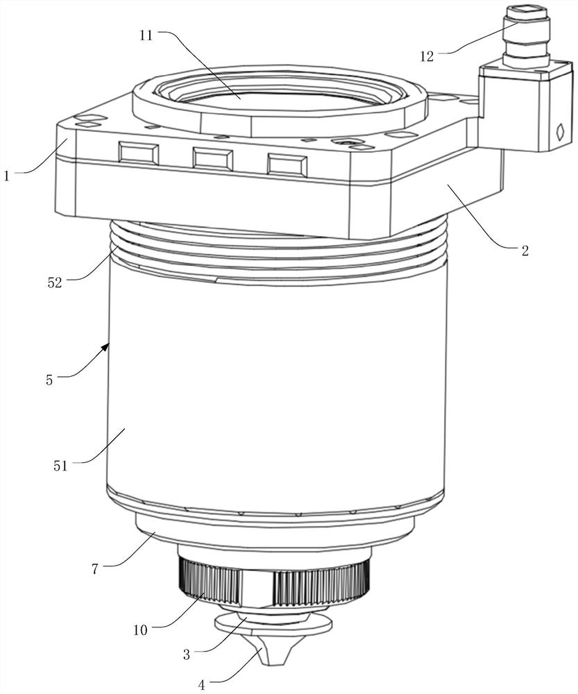
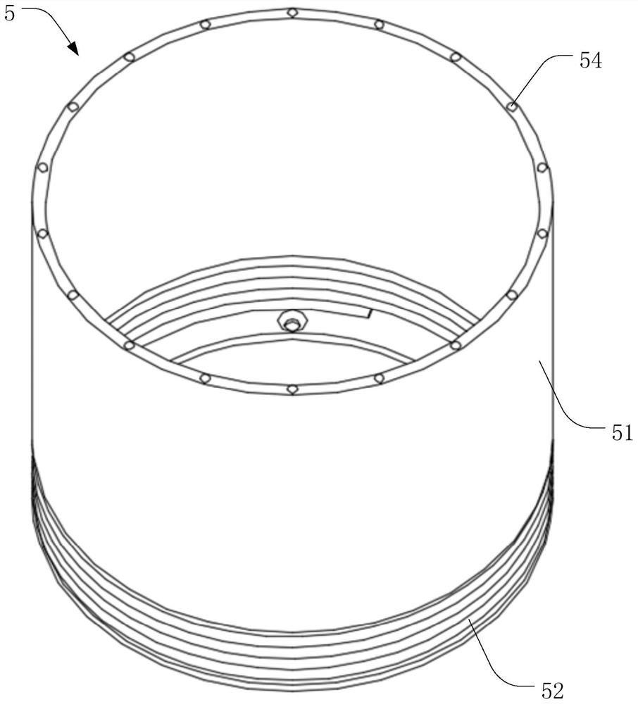
The invention belongs to the technical field of laser cutting, and particularly relates to capacitance sensing equipment and a laser cutting head. The capacitance sensing equipment comprises a mounting seat, a capacitance sensor, a ceramic ring, a nozzle and a collision protection device, the mounting seat is mounted on the capacitance sensor, the ceramic ring is mounted at one end, far away from the mounting seat, of the capacitance sensor, and the nozzle is mounted at one end, far away from the capacitance sensor, of the ceramic ring; the collision protection device comprises a protection sleeve and a first elastic piece, the protection sleeve is connected to the capacitance sensor in a sleeving mode, one end of the first elastic piece is connected with the protection sleeve, and the other end of the first elastic piece is connected with the capacitance sensor; and a side collision buffer space is formed between the inner side wall of the protection sleeve and the outer side wall of the capacitance sensor. The capacitance sensing equipment is simple in structure, small in size, low in manufacturing cost and good in anti-collision capability.

Description

technical field [0001] The invention belongs to the technical field of laser cutting, in particular to a capacitance sensing device and a laser cutting head. Background technique [0002] With the continuous development of laser technology, the application of laser cutting technology is becoming more and more extensive. In the process of laser cutting, a capacitance value will be generated between the capacitive sensing device and the workpiece to be cut. Through the processing of this capacitance value, the distance between the capacitive sensing device and the surface of the workpiece can be guaranteed, thus solving the problem of the capacitive sensing device and the surface of the workpiece. The problem of collision between workpieces to be cut can be solved, and the quality of laser cutting can also be improved. [0003] When the laser cutting head emits cutting laser light through the capacitive sensing device for laser cutting of the workpiece to be cut, the capaciti...

Claims


Application Information

Patent Timeline
Patent Type & Authority Applications(China)
IPC IPC(8): B23K26/08B23K26/38B23K26/70
CPCB23K26/38B23K26/08B23K26/702
Inventor 肖球温旺古封雨鑫王小华王伟封雪霁方光强陈焱高云峰
Owner HANS LASER TECH IND GRP CO LTD
Learn More