
Field welding tool for traveling I-shaped beam and assembling and welding method of field welding tool

An I-shaped beam and on-site welding technology, applied in welding equipment, auxiliary welding equipment, welding/cutting auxiliary equipment, etc., can solve the problems of easy deformation of the flange plate, reduce welding deformation, save costs, and be easy to operate Effect

Pending Publication Date: 2021-10-22
SHANXI ELECTRIC POWER CONSTR CO LTD CEEC
View PDF0 Cites 0 Cited by
  • Summary
  • Abstract
  • Description
  • Claims
  • Application Information

AI Technical Summary

Problems solved by technology

[0003] The invention provides an on-site welding tooling for a traveling I-shaped beam and an assembly and welding method thereof, which solves the technical problem that the flange plate is easily deformed when the web plate and the flange plate of the traveling I-shaped beam are welded

Method used


Image

  • Field welding tool for traveling I-shaped beam and assembling and welding method of field welding tool
  • Field welding tool for traveling I-shaped beam and assembling and welding method of field welding tool
  • Field welding tool for traveling I-shaped beam and assembling and welding method of field welding tool

Examples


Embodiment Construction

[0021] The present invention is described in detail below in conjunction with accompanying drawing:

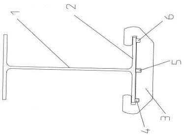
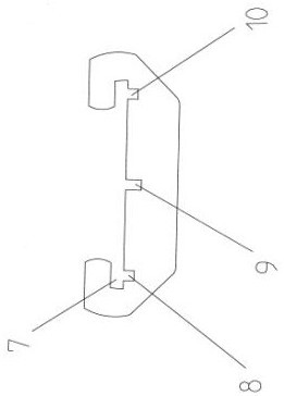
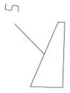
[0022] An on-site welding tool for traveling I-shaped beams in a steam turbine house, including a web 1, a lower flange 2 and an upper flange, the web 1, the lower flange 2 and the upper flange are connected by spot welding For an I-shaped beam, an anti-deformation fixture plate 3 is sleeved on the lower flange plate 2, and an inverted T-shaped groove 7 is arranged on the top surface of the anti-deformation fixture plate 3. Left positioning wedge embedded groove 8, middle positioning wedge embedded groove 9 and right positioned wedge embedded groove 10 are respectively provided on the groove bottom surface of the groove, and left positioning wedge embedded groove 8 is provided with left positioning wedge Block 4, the upper top surface of the left positioning wedge block 4 is connected to the lower bottom surface of the lower flange plate 2, and the middle positioning wedge blo...


PUM


Abstract

The invention discloses a field welding tool for a traveling I-shaped beam and an assembling and welding method of the field welding tool. The problem that a flange plate is prone to deformation when a web and the flange plate of the traveling I-shaped beam are welded is solved. A lower flange plate (2) is sleeved with anti-deformation clamp plates (3); an inverted-T-shaped groove (7) is formed in the top face of each anti-deformation clamp plate (3); a left positioning wedge block embedding groove (8), a middle positioning wedge block embedding groove (9) and a right positioning wedge block embedding groove (10) are formed in the groove bottom face of each inverted-T-shaped groove (7); wedge blocks are arranged in the three grooves correspondingly; the upper top faces of the wedge blocks are connected to the lower bottom face of the lower flange plate (2) in an abutting manner; and the lower flange plate (2) is sleeved with the anti-deformation clamp plates (3) at intervals in the front-back longitudinal direction of the web (1). Welding deformation of the flange plate is greatly reduced, and straightening of the I-shaped beam obtained through subsequent welding is omitted.

Description

technical field [0001] The invention relates to a welding tool, in particular to an on-site welding tool for an I-shaped beam used in a steam turbine room of a thermal power plant and a method for assembling and welding the tool. Background technique [0002] In the equipment installation of the steam turbine room of a newly-built thermal power plant, it is necessary to set up a driving beam for driving on the top of the machine room. The driving beam is an I-shaped beam, which is generally completed on-site with steel plate processing and welding. The on-site production process is as follows: first The web, upper flange and lower flange of the I-shaped beam are processed separately with steel plates, and the three steel plates are spot welded together to form the I-shaped beam. At the joint with the web, perform groove connection welding of the welds on both sides; during groove welding, because the flange plate on the outer side of the weld is narrow, the welding heat is r...

Claims


Application Information

Patent Timeline
IPC IPC(8): B23K37/04B23K37/02
CPCB23K37/04B23K37/0443B23K37/02B23K37/0211
Inventor 李军连小如银婧彤赵勇朱彤徐鸿雁
Owner SHANXI ELECTRIC POWER CONSTR CO LTD CEEC
Learn More