Full-degree-of-freedom air pressure floating type deburring device

A deburring and degree of freedom technology, applied in the direction of grinding/polishing safety devices, grinding machine parts, metal processing equipment, etc., can solve the problems of spindle shaking, internal jamming of the device, and affecting the device, so as to improve work efficiency , increase the stability, increase the effect of sensitivity

Inactive Publication Date: 2021-10-22
广东昭武智能装备有限公司
View PDF0 Cites 0 Cited by
  • Summary
  • Abstract
  • Description
  • Claims
  • Application Information

AI Technical Summary

Problems solved by technology

[0006] The present invention provides a full-degree-of-freedom pneumatic floating deburring device. One of the purposes is to have the function of increasing the stability of the device and solve the problem of poor stability of the deburring device, so that the main shaft of the deburring device shakes during the deburring operation, resulting in deburring. The effect of the burr is reduced, which affects the working efficiency of the burr device; another purpose is to solve the problem that waste and dust are easy to enter the interior of the device, which makes the interior of the device jammed and affects the normal operation of the device, so as to increase dust prevention The function of improving the service life of the device

Method used


Image

  • Full-degree-of-freedom air pressure floating type deburring device
  • Full-degree-of-freedom air pressure floating type deburring device
  • Full-degree-of-freedom air pressure floating type deburring device

Examples


Embodiment 1

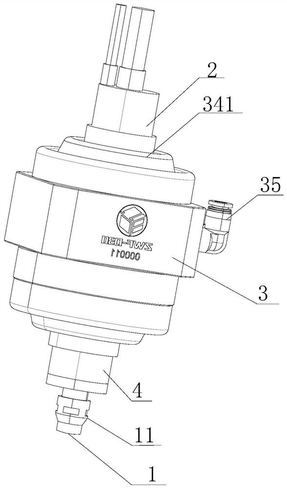
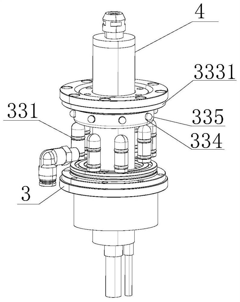
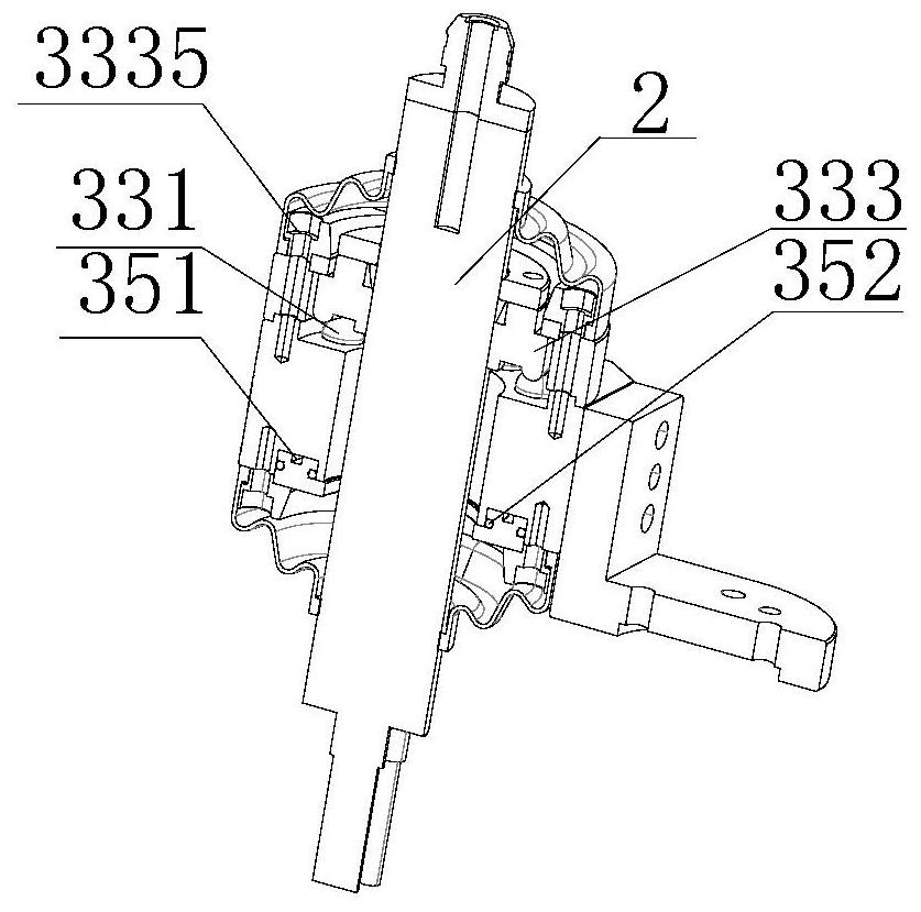
[0041] Such as Figure 1-7 As shown, the present invention provides a full-degree-of-freedom pneumatic floating deburring device, which includes a deburring device main body 1, a main shaft 2, a middle shaft layer 3, and a bottom shaft 4. The top of the deburring device main body 1 is movably connected with a connecting shaft 11. The bottom shaft 4 is installed on the top of the connecting shaft 11, the middle shaft layer 3 is fixedly installed on the top of the bottom shaft 4, the main shaft 2 is fixedly installed on the inner side of the middle shaft layer 3, and the sealing shaft 31 is fixedly installed on the top of the middle shaft layer 3 , the top of the sealing shaft 31 is fixedly installed with a connecting column 32, the inside of the middle shaft layer 3 is fixedly installed with a stabilizing mechanism 33, the top and bottom of the middle shaft layer 3 are fixedly installed with a dust-proof shaft 34, and the stabilizing mechanism 33 includes a moving piston 331 , ...

Embodiment 2

[0044] Such as Figure 1-7 As shown, on the basis of Embodiment 1, the present invention provides a technical solution: preferably, the top of the limit shaft 3331 is provided with a limit hole 3330, and the inner side of the pressure ring 3332 is fixedly installed with a collar block, and the inner side of the collar block is fixed. A hoop 3333 is installed, and the inner side of the pressure ring 3332 is fixedly installed with a hoop 3333 , and the inner side of the hoop 3333 is fixedly installed on the outer side of the main shaft 2 .

[0045] In this embodiment, the limit block is plugged into the limit hole 3330, so that the limit shaft 3331 reaches the limit and fixation of the main shaft 2, and then the collar block and the hoop 3333 cooperate with each other to increase the support for the main shaft. 2 is fixed to prevent the main shaft 2 from shaking left and right during operation, resulting in a decrease in accuracy, so that the main shaft 2 can stably drive the ma...

Embodiment 3

[0047] Such as Figure 1-7 As shown, on the basis of Embodiment 1, the present invention provides a technical solution: preferably, a dustproof cover 341 is fixedly installed inside the dustproof shaft 34, and a fixed shaft 342 is fixedly installed at the bottom of the dustproof cover 341 to prevent The interior of the dust cover 341 is fixedly installed with an adsorption column 3411 , and fixed blocks 3412 are fixedly installed at both ends of the adsorption column 3411 , and the other side of the fixed block 3412 is fixedly installed on the inner wall of the dust cover 341 . The outer side of the fixed shaft 342 is provided with a fixed hole 3421 , and the inside of the fixed shaft 342 is fixedly sleeved with a retaining ring 3422 .

[0048] In this embodiment, debris and dust are filtered and blocked by the dust cover 341 at both ends of the central axis layer 3, and then the adhesion of the surface of the adsorption column 3411 is combined to adhere to the finer dust ente...


PUM


Abstract

The invention discloses a full-degree-of-freedom air pressure floating type deburring device, and relates to the technical field of machining device. The full-degree-of-freedom air pressure floating type deburring device comprises a deburring device body, a main shaft, a middle shaft layer and a bottom shaft, the top of the deburring device body is movably connected with a connecting shaft, the bottom shaft is arranged at the top of the connecting shaft, and the middle shaft layer is fixedly installed at the top of the bottom shaft; a main shaft is fixedly installed on the inner side of the middle shaft layer, and a sealing shaft is fixedly installed on the top of the middle shaft layer. According to the full-degree-of-freedom air pressure floating type deburring device, through mutual cooperation of an air inlet pipe and an air inlet hole, air is injected into the air inlet pipe and enters an air pressure chamber through the air inlet hole, so that the function of increasing the internal air pressure is achieved, a mounting block is ejected out through the internal air pressure by a movable piston, then the function of adjusting the floating force is achieved through the amount of the injected air, the problem that the internal buoyancy of the device cannot be controlled, so that the sensitivity of spindle movement is reduced is solved, the sensitivity of the spindle is improved, and the deburring effect is better.

Description

technical field [0001] The invention relates to the technical field of mechanical processing devices, in particular to a full-degree-of-freedom pneumatic floating deburring device. Background technique [0002] In the field of mechanical processing, it is usually necessary to remove the burrs generated after processing on parts. The commonly used deburring methods include magnetic deburring, plasma polishing deburring, vibration polishing and air pressure polishing. [0003] There are following problems at prior art: [0004] 1. The stability of the existing deburring device is poor, which causes the main shaft to shake during the deburring operation of the deburring device, which reduces the effect of deburring and thus affects the working efficiency of the deburring device; [0005] 2. In the process of deburring, a large amount of waste is likely to be generated, so that under the action of the deburring device, waste and dust will enter the interior of the device, resul...

Claims


Application Information

Patent Timeline
Patent Type & Authority Applications(China)
IPC IPC(8): B24B41/04B24B55/06B24B55/00
CPCB24B41/04B24B55/06B24B55/00
Inventor 容利邵基锋
Owner 广东昭武智能装备有限公司
Why Eureka
Try Eureka