
Building board pouring equipment

A technology for building boards and equipment, applied in the field of building boards, can solve the problems of prolonged board forming time, low pouring efficiency, increased bubble generation, etc., so as to improve pouring and forming efficiency, improve cleaning effect and efficiency, and improve uniformity. Effect

Inactive Publication Date: 2021-10-22
GUANGZHOU CITY CONSTR COLLEGE
View PDF0 Cites 1 Cited by
  • Summary
  • Abstract
  • Description
  • Claims
  • Application Information

AI Technical Summary

Problems solved by technology

However, in the existing slab pouring device, in order to avoid scattering, most of its pouring heads are thin cylindrical heads, so that the grout sprayed inside the slab frame is in the process of falling and falling into the slab frame. It is easy to generate a large number of air bubbles, but in order to improve the strength and toughness of the plate, a steel frame is often built inside the plate frame, so that the amount of air bubbles generated during the slurry drop process increases, and then when it is polished and driven , can only be polished on its surface, thus prolonging the forming time of the plate, and its pouring efficiency is not high

Method used


Image

  • Building board pouring equipment
  • Building board pouring equipment
  • Building board pouring equipment

Examples


Embodiment Construction

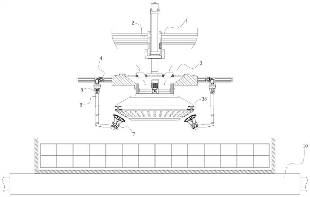
[0050] refer to figure 1 , the present invention provides a technical solution: a building plate pouring equipment, which includes:

[0051] Conveyor belt 10 for conveying sheet metal frames;

[0052] The lifting assembly 2 is slidably connected to the transverse guide rail 1;

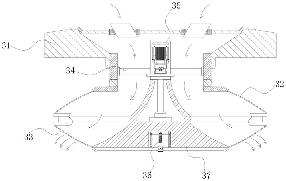
[0053] The pouring device 3 is installed on the output end of the lifting assembly 2, and a side lateral moving device 4 is installed on the left and right sides;

[0054] The lifting arm 6 is provided with two groups, which are respectively installed on the side lateral moving device 4, and are driven by the rotating motor 5 to rotate;

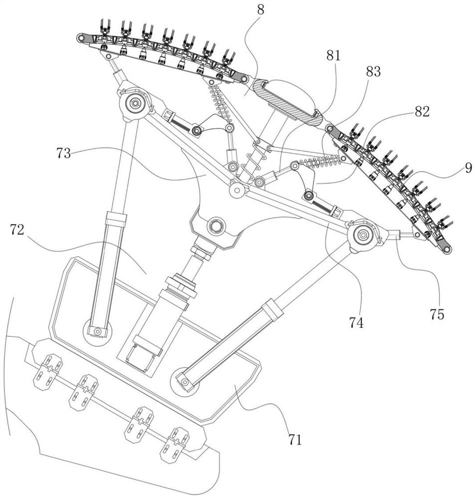
[0055] The cleaning device 7 is provided with two groups, respectively installed on the output end of the lifting arm 6;

[0056] Wherein, the lifting arm adjusts the height of the cleaning device, and the rotating motor adjusts the external rotation of the lifting arm to stop operation, and the internal rotation to start operation.

[0057] In this embodiment, th...


PUM


Abstract

The invention discloses building board pouring equipment. The building board pouring equipment comprises a conveying belt used for conveying plate frames; a lifting assembly slidably connected to a transverse guide rail; a pouring device mounted at the output end of the lifting assembly, wherein side transverse moving devices are mounted on the left side and the right side of the pouring device; two groups of lifting arms respectively mounted on the side transverse moving devices and driven by a rotating motor to rotate; and two sets of cleaning devices installed at the output ends of the lifting arms correspondingly.

Description

technical field [0001] The invention relates to the technical field of building boards, in particular to a building board pouring equipment. Background technique [0002] At present, in the process of building construction, in some construction processes, the plates that have been poured can be directly spliced ​​or constructed to improve construction efficiency. However, in the existing slab pouring device, in order to avoid scattering, most of its pouring heads are thin cylindrical heads, so that the grout sprayed inside the slab frame is in the process of falling and falling into the slab frame. It is easy to generate a large number of air bubbles, but in order to improve the strength and toughness of the plate, a steel frame is often built inside the plate frame, so that the amount of air bubbles generated during the slurry drop process increases, and then when it is polished and driven , can only be polished on its surface, thus prolonging the forming time of the plate...

Claims


Application Information

Patent Timeline
IPC IPC(8): B28B1/087B28B1/20B28B11/08B28B7/38B28B13/06
CPCB28B1/087B28B1/20B28B11/0845B28B7/386B28B13/067
Inventor 刘国强鲁周静
Owner GUANGZHOU CITY CONSTR COLLEGE
Learn More