Reversible conveying mechanism for circuit board production and conveying

A technology of conveying mechanism and reversing mechanism, which is applied in the direction of conveyor objects, transportation and packaging, roller table, etc., which can solve the problems of affecting work efficiency, large occupied area, and increased cost, and achieves convenient control, small occupied area, and high work efficiency. The effect of improving efficiency

Pending Publication Date: 2021-10-22
QUZHOU CHUANTE ELECTRONICS TECH CO LTD
View PDF14 Cites 8 Cited by
  • Summary
  • Abstract
  • Description
  • Claims
  • Application Information

AI Technical Summary

Problems solved by technology

[0002] Circuit boards are also called printed circuit boards and printed circuit boards, and are called PCB boards in English; circuit boards can be divided into single-panel, double-panel and multi-layer boards. , the powder needs to be washed off after punching, and it needs to be dried after cleaning. This is all done through assembly line operations; the circuit board without electronic components is usually called a circuit substrate, and the circuit substrate needs to be transported to different positions through a conveying device. The movement usually uses the conveyor belt to convey the circuit board. The existing circuit board conveying device can only provide transportation in one direction or in two directions, but there are many equipments used in the circuit board processing process. Conveyor belts need to be installed between the room and other equipment (i.e. equipment in the front and rear processing procedures), but using this transportation method requires multiple conveyor belts, which not only increases the cost, occupies a large area, and is inconvenient to control, seriously affecting work efficiency

Method used


Image

  • Reversible conveying mechanism for circuit board production and conveying
  • Reversible conveying mechanism for circuit board production and conveying
  • Reversible conveying mechanism for circuit board production and conveying

Examples


Embodiment 1

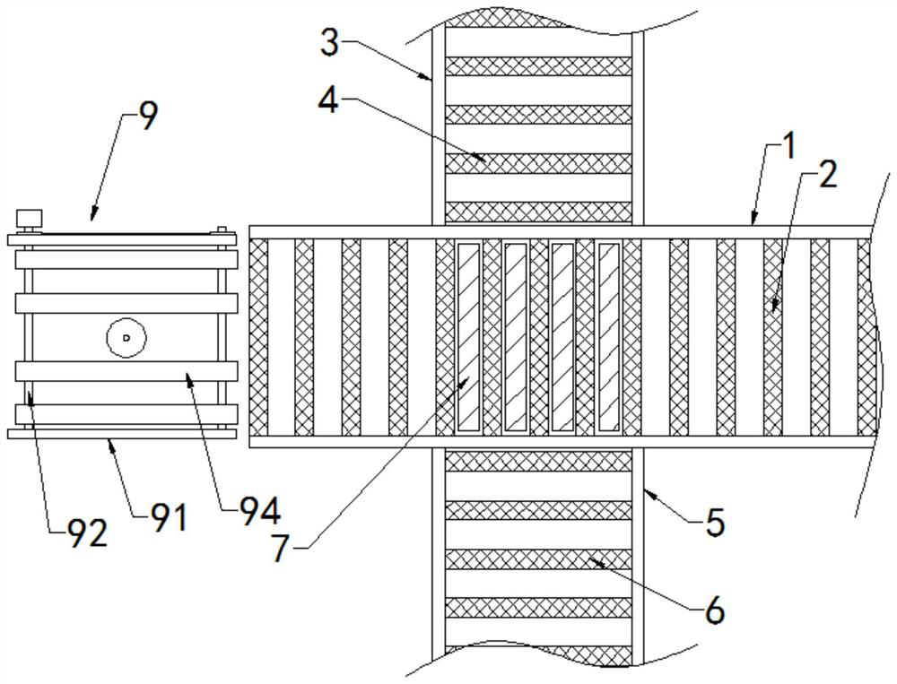
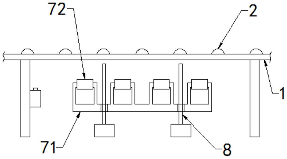
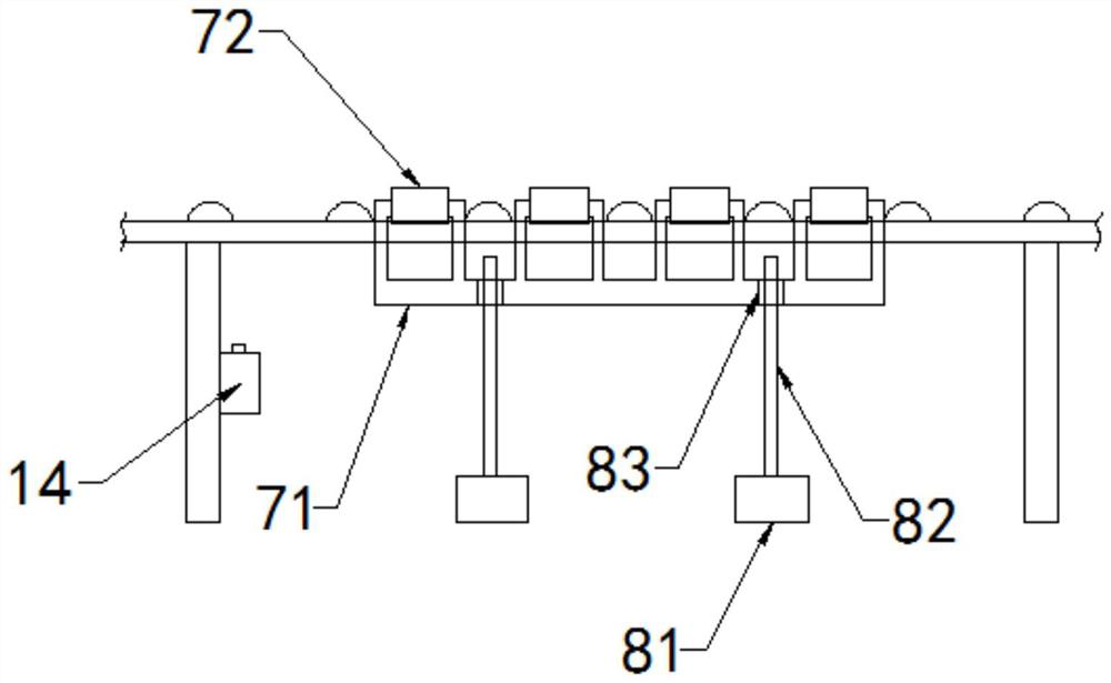
[0031] Such as Figure 1 to Figure 4 As shown, the present invention discloses a reversible conveying mechanism for the production and conveying of circuit boards. In a specific embodiment of the present invention, it includes a first conveying bracket 1 horizontally arranged on the left and right, and on the first conveying bracket 1 There are first conveying rollers 2 and a first driving mechanism for controlling the forward and reverse rotation of the first conveying rollers 2, and the first conveying rollers 2 are arranged at intervals, and the left side of the first conveying bracket 1 is connected with a rotating plate Mechanism 9, the rotating plate mechanism 9 is used to transport the circuit board to the first conveying roller 2 and rotate the circuit board; one side of the first conveying support 1 is vertically provided with a second conveying support 3, the The second conveying support 3 is provided with a second conveying roller and a second driving mechanism for ...

Embodiment 2

[0040] Such as Figure 5 and Figure 6 As shown, the difference between this embodiment and Embodiment 1 is that, in this embodiment, the rotating plate mechanism 9 also includes an adsorption unit 10, and the adsorption unit 10 includes two sides of the cylinder 97 with Two elastic balls 101 in the air cavity, the upper and lower ends of the elastic balls 101 are fixedly connected with the horizontal plate 96 and the mounting seat 95 respectively, the rotating rod 99 is set as a hollow structure, and the upper end of the rotating rod 99 is open, the The elastic ball 101 communicates with the rotating rod 99 through the air pipe 102; when the cylinder 97 drives the supporting plate 991 to be positioned at the upper end of the second conveyor belt 94, the elastic ball 101 is a sphere; At this time, the elastic ball 101 is compressed by the horizontal plate 96 to form an oblate spheroid.

[0041] Through the above technical scheme, when the cylinder does not control the rising...

Embodiment 3

[0046] Such as Figure 7 and Figure 8 As shown, the difference between this embodiment and Embodiment 1 is that, in this embodiment, a correcting mechanism 11 is provided on the upper end of the first conveying roller 2 on the first conveying frame, and the correcting mechanism 11 includes setting Fixed plates 111 on both sides of the first conveying roller 2, the fixed plates 111 are fixed on the first conveying support 1, and the end of the fixed plate 111 facing the first conveying roller 2 is provided with a film body 112, the film body 112 A cavity that can be filled with gas is provided inside, and a correction channel 113 is formed between the membrane bodies 112 on both sides, and the width of the correction channel 113 gradually decreases from the input end to the output end of the first delivery stent 1 .

[0047] In this embodiment, a rubber layer 114 is provided on the side of the membrane body 112 facing the middle of the first conveying roller 2 .

[0048] In ...


PUM


Abstract

According to the technical scheme, a reversible conveying mechanism for circuit board production and conveying is characterized by comprising a first conveying support which is transversely arranged left and right, first conveying rollers and a first driving mechanism are arranged on the first conveying support, the first conveying rollers are arranged at intervals, and the left side of the first conveying support is connected with a rotating plate mechanism; a second conveying support is vertically arranged on one side of the first conveying support, a second conveying roller and a second driving mechanism are arranged on the second conveying support, a third conveying support is arranged on one side of the first conveying support, a third conveying roller and a third driving mechanism are arranged on the third conveying support, and reversing mechanisms are arranged at the lower ends of the first conveying rollers and are used for transferring circuit boards on the first conveying rollers to the second conveying roller or the third conveying roller. The reversible conveying mechanism has the beneficial effects that reversible conveying can be achieved, and the orientation position of the circuit boards can be adjusted.

Description

technical field [0001] The invention relates to the technical field of circuit board conveyance, in particular to a reversible conveying mechanism for circuit board production and conveyance. Background technique [0002] Circuit boards are also called printed circuit boards and printed circuit boards, and are called PCB boards in English; circuit boards can be divided into single-panel, double-panel and multi-layer boards. , the powder needs to be washed off after punching, and it needs to be dried after cleaning. This is all done through assembly line operations; the circuit board without electronic components is usually called a circuit substrate, and the circuit substrate needs to be transported to different positions through a conveying device. The movement usually uses the conveyor belt to convey the circuit board. The existing circuit board conveying device can only provide transportation in one direction or in two directions, but there are many equipments used in the...

Claims


Application Information

Patent Timeline
Patent Type & Authority Applications(China)
IPC IPC(8): B65G47/64B65G47/22B65G47/91B65G13/12
CPCB65G47/642B65G13/12B65G47/914B65G47/22
Inventor 兰胜有兰凌晓雪龚小林王彬吕飞章建荣刘春红
Owner QUZHOU CHUANTE ELECTRONICS TECH CO LTD
Why Eureka
Try Eureka