Rotary PDC drill bit
A drill bit and deflection angle technology, applied in construction and other directions, can solve the problems of short service life, shortened life, and high cost of drill bits, and achieve the effects of saving drilling costs, improving drill life, and high drilling speed.
- Summary
- Abstract
- Description
- Claims
- Application Information
AI Technical Summary
Problems solved by technology
Method used
Image
Examples
Embodiment 1
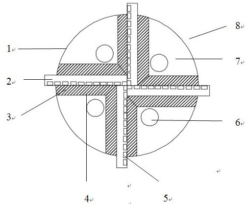
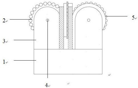
[0019] Refer to attached figure 1 and 2 , a rotary PDC drill bit, including a drill base 1, a blade 2, a PDC cutting tooth 5, a nozzle 6, a flow channel 7, a blade support seat 3 and a blade rolling shaft 4, wherein: the nozzle 6 is embedded in the drill base 1 Above, the PDC cutting teeth 5 are arranged on the blade 2, and the blade supporting base 3 is fixed on the drill base 1; the blade 2 is fixed on the blade supporting base 3 through the blade rolling shaft 4, and the blade 2 surrounds the blade The wing rolling shaft 4 rotates freely;
Embodiment 2
[0021] On the basis of embodiment 1, further include:
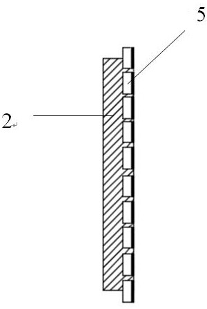
[0022] The PDC cutting teeth 5 are arranged on the outermost side of the blade 2 with a deflection angle of 5°, 10°, or 25° relative to the blade 2 .
[0023] The PDC cutting teeth 5 are not arranged on the same track relative to the disc center of the blade 2, and adjacent PDC cutting teeth 5 have a fixed exposure difference. Or the PDC cutting teeth 5 are arranged on the same track relative to the disc center of the blade 2, and adjacent PDC cutting teeth 5 have unfixed exposure differences.
[0024] There are multiple blades 2 , and each blade 2 is equipped with a blade support seat 3 on both sides.
Embodiment 3
[0026] A rotary PDC drill bit is mainly composed of a drill base body 1, a blade 2, a blade support seat 3, a blade rolling shaft 4, a PDC cutting tooth 5, a nozzle 6 and a flow channel chip removal groove 7. The nozzle 6 is embedded on the drill base 1, the blade 2 is fixed on the drill base 1 through the blade rolling shaft 4 and the blade support seat 3, and the PDC cutting teeth 5 are arranged on each blade 2, and the blade 2 is the center A disc blade with a through hole. Drill bit arrangement method: PDC cutting teeth 5 are arranged on the outermost side of each blade 2 disk, and the maximum distance between PDC cutting teeth 5 and the center of the disk is greater than the radius of the disk.
PUM
 Abstract
Description
Claims
Application Information
 - R&D
- Intellectual Property
- Life Sciences
- Materials
- Tech Scout
- Unparalleled Data Quality
- Higher Quality Content
- 60% Fewer Hallucinations
Browse by: Latest US Patents, China's latest patents, Technical Efficacy Thesaurus, Application Domain, Technology Topic, Popular Technical Reports.
© 2025 PatSnap. All rights reserved.Legal|Privacy policy|Modern Slavery Act Transparency Statement|Sitemap|About US| Contact US: help@patsnap.com


