A moving coil type self-driven maglev guide rail device and its control method

The technology of a guide rail device and control method, which is applied in the field of moving coil self-driven maglev guide rail device and its control, can solve the problems that high-performance guide rails cannot be driven by themselves, high stiffness and straightness are difficult to control, and single workplaces, etc., to achieve improvement Performance indicators, simple and compact structure, and the effect of improving control accuracy

Active Publication Date: 2022-02-08
HARBIN INST OF TECH
View PDF10 Cites 0 Cited by
  • Summary
  • Abstract
  • Description
  • Claims
  • Application Information

AI Technical Summary

Problems solved by technology

[0007] The purpose of the present invention is to provide a moving coil type self-driven magnetic levitation guide rail device and its control method to solve the problem that the existing high-performance guide rail cannot be driven by itself, cannot work in a vacuum environment, has a single workplace, and is difficult to control high rigidity and straightness question

Method used


Image

  • A moving coil type self-driven maglev guide rail device and its control method
  • A moving coil type self-driven maglev guide rail device and its control method
  • A moving coil type self-driven maglev guide rail device and its control method

Examples


specific Embodiment approach 1

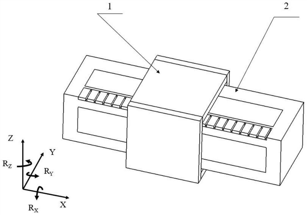
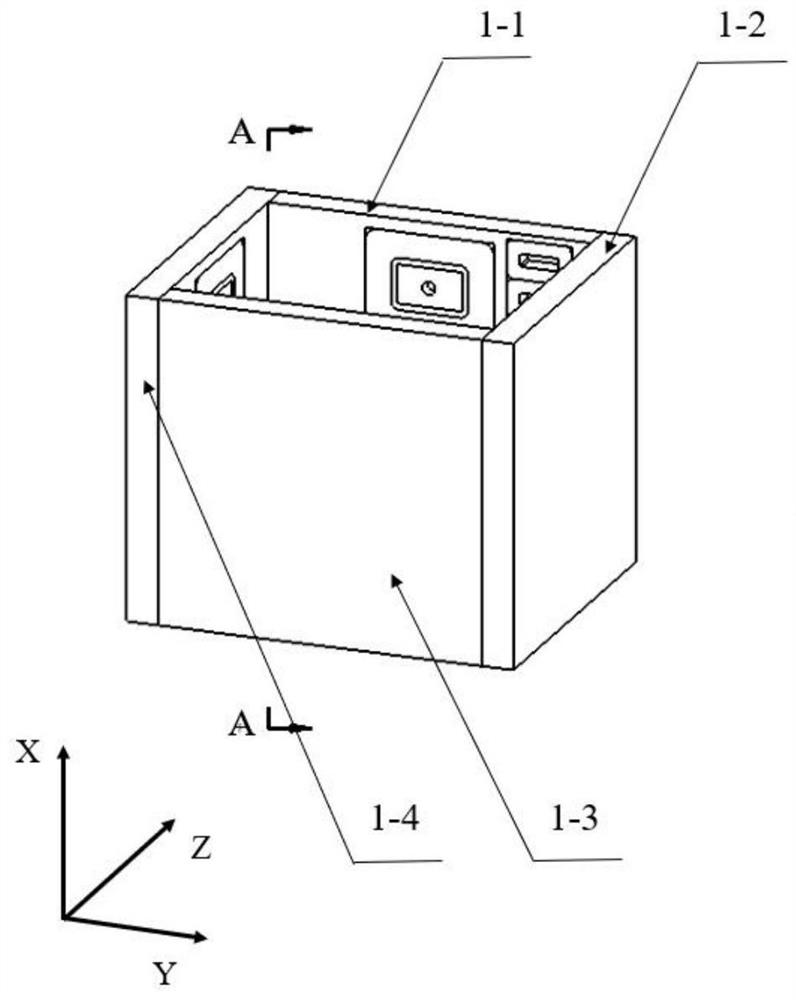
[0030] Specific implementation mode one: combine Figure 1-Figure 5 Note that this embodiment discloses a moving coil type self-driven magnetic levitation guide rail device, including a guide sleeve 1 and a guide shaft 2, the guide sleeve 1 is sleeved on the guide shaft 2; the guide sleeve 1 includes a coil winding 1- 6. Four guide sleeve support frames and four E-shaped components 1-5; the guide shaft 2 includes a guide shaft support frame 2-1, a permanent magnet 2-3 and four I-type electromagnets 2-2; each The E-type assembly 1-5 includes a bipolar electromagnet 1-5-4, a primary coil 1-5-1, an induction coil 1-5-2, an eddy current sensor 1-5-5 and two Hall elements 1-5-3;

[0031]The four guide sleeve support frames are combined to form a square sleeve, and the centers of the inner sides of the four guide sleeve support frames are respectively packaged with E-type components (and arranged symmetrically), and the four E-type components are all along the length direction of t...

specific Embodiment approach 2

[0035] Specific implementation mode two: as Figure 1-Figure 5 As shown, this embodiment is a control method for realizing a moving coil self-driving maglev guideway by using the moving coil self-driving maglev guideway device described in Embodiment 1. The control method is as follows:

[0036] By adjusting the current size of the two-stage primary coil 1-5-1 of the E-shaped component 1-5 packaged on the inner side of the upper and lower guide sleeve support frames of the guide sleeve 1, and making the currents different, the guide sleeve 1Z can be realized The adjustment of the degree of freedom (that is, by adjusting the current size of the primary coil 1-5-1 of the E-type assembly 1-5 that is packaged on the side of the first guide bush support frame 1-1 and the third guide bush support frame 1-3 , can realize the adjustment of the 1Z degree of freedom of the guide sleeve. It is required that the currents of the two-stage primary coils 1-5-1 encapsulated in the side of the...


PUM


Abstract

A moving coil type self-driven maglev guide rail device and a control method thereof belong to the technical field of high-end equipment. Four guide sleeve support frames are combined to form a square sleeve, and the centers of the inner sides of the four guide sleeve support frames are respectively packaged with E-shaped components, and the coil windings are packaged on the inner side of the upper guide sleeve support frame, and are located One side of the component; four I-type electromagnets are respectively packaged on the four sides of the guide shaft support frame, the four I-type electromagnets are arranged opposite to the four E-type components, and the permanent magnets are packaged on the guide shaft support On the upper side of the frame, the permanent magnet and the coil winding are arranged oppositely; the bipolar electromagnet is E-type, and the two Hall elements are installed at the center of the two-stage pole faces of the bipolar electromagnet, and the induction coil is wound on the two-stage of the bipolar electromagnet. On the surface, the primary coil is wound on the surface of the two-stage induction coil of the bipolar electromagnet, and the eddy current sensor is installed at the center of the middle tooth of the bipolar electromagnet. The invention is used in ultra-precision systems.

Description

technical field [0001] The invention belongs to the technical field of high-end equipment, and in particular relates to a moving coil type self-driving maglev guide rail device and a control method thereof. Background technique [0002] Compared with traditional contact guide rails, air bearing guide rails use air as a form of support. They have the advantages of no contact wear and no mechanical friction during work, and can achieve higher-precision positioning movements. Therefore, linear motors+ The driving form of air bearing guide rail is widely used in ultra-precision motion system at present. However, with the development of the next generation of high-end equipment towards high speed, precision and modularization, and the need for a vacuum working environment, further, higher requirements are placed on the high rigidity, straightness and multiple working scenarios of the linear guide. However, the air-floating guide rail has a lag in air gap adjustment and a slow re...

Claims


Application Information

Patent Timeline
Patent Type & Authority Patents(China)
IPC IPC(8): F16C32/04
CPCF16C32/0446F16C32/0459F16C32/0451F16C32/0487
Inventor 刘杨缪骞宋法质
Owner HARBIN INST OF TECH
Why Eureka
Try Eureka