Unlock instant, AI-driven research and patent intelligence for your innovation.

Rotating shaft assembly, axial magnetic suspension locating structure for rotating shaft, compressor and air conditioner

A technology of axial positioning and positioning structure, applied in the field of compressor manufacturing, can solve the problems of low reliability of magnetic suspension system, large radial fluctuation of thrust plate, easy deformation of thread teeth, etc., so as to improve assembly or maintenance efficiency and locate assembly structure. Simple, reliable effect of axial radial positioning

Pending Publication Date: 2021-10-22
GREE ELECTRIC APPLIANCES INC OF ZHUHAI
View PDF0 Cites 0 Cited by
  • Summary
  • Abstract
  • Description
  • Claims
  • Application Information

AI Technical Summary

Problems solved by technology

The thrust plate 30 is the core bearing part of the axial suspension control of the rotating shaft 10, and has high precision requirements for its radial and axial positioning. Positioning, the thrust disc, lock nut and the shaft are threaded. When the thrust disc bears a large axial load, due to the gap between the threaded parts, the axial movement of the thrust disc is large and the axial suspension accuracy is low;② The thrust plate realizes radial fixed support through the threaded step and the support ring. There is a gap in the threaded connection, and when the threaded step bears a large radial load, the thread tooth is easily deformed. When the rotating shaft runs at high speed, the radial fluctuation of the thrust plate is large, and the magnetic suspension system low reliability

Method used


Image

  • Rotating shaft assembly, axial magnetic suspension locating structure for rotating shaft, compressor and air conditioner
  • Rotating shaft assembly, axial magnetic suspension locating structure for rotating shaft, compressor and air conditioner
  • Rotating shaft assembly, axial magnetic suspension locating structure for rotating shaft, compressor and air conditioner

Examples


Embodiment Construction

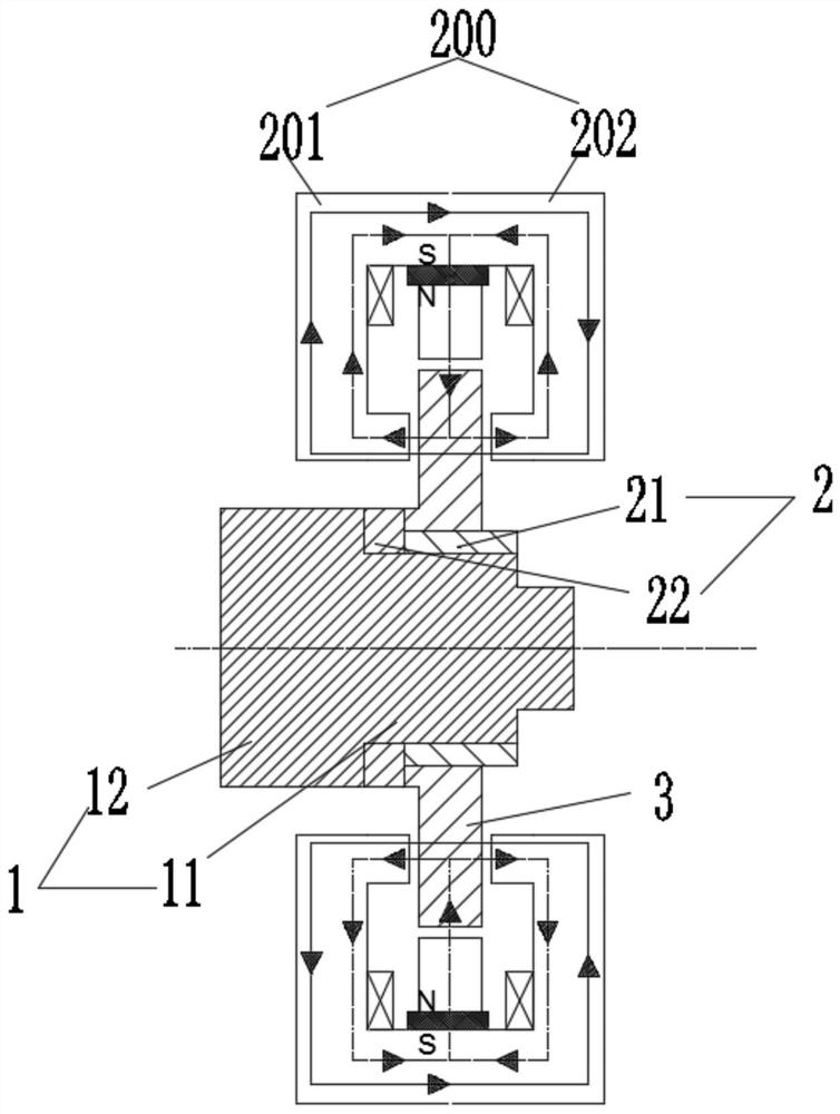
[0023] see in conjunction Figure 1 to Figure 3 As shown, according to the embodiment of the present invention, a rotating shaft assembly is provided, including a rotating shaft 1, the rotating shaft 1 includes a first shaft segment 11, and a positioning sleeve 2 is fitted on the first shaft segment 11, and the positioning sleeve The barrel 2 has a radially positioned barrel section 21 that is interference-fitted with the first shaft section 11 , and the outer periphery of the radially positioned barrel section 21 is fitted with a thrust disc 3 . In this technical solution, the thrust plate 3 , the radial positioning cylinder section 21 and the rotating shaft 1 are radially fitted together through an interference fit. The radial or axial movement caused by the existing backlash makes the axial and radial positioning of the thrust plate 3 more reliable, and when it is used in conjunction with the magnetic bearing, it can improve the levitation accuracy of the magnetic bearing; ...


PUM


Abstract

The invention provides a rotating shaft assembly, an axial magnetic suspension locating structure for a rotating shaft, a compressor and an air conditioner. The rotating shaft assembly comprises the rotating shaft, wherein the rotating shaft comprises a first shaft section, the first shaft section is sleeved with a locating sleeve, and the locating sleeve is provided with a radial locating sleeve section which is sleeved with the first shaft section in an interference mode; and the periphery of the radial locating sleeve section is sleeved with a thrust disc in an interference mode. According to the invention, the occurrence of a radial leaping phenomenon or an axial leaping phenomenon caused by tooth gaps existing in threaded piece connection in the prior art can be avoided, axial locating and radial locating for the thrust disc is more reliable, when the thrust disc bears a large load, the thrust disc does not deform like threaded teeth in the prior art, and therefore, the thrust disc is ensured not to generate radial fluctuation; and a locating assembly structure is simpler, so that the assembly efficiency or the maintenance efficiency is increased.

Description

technical field [0001] The invention belongs to the technical field of compressor manufacturing, and in particular relates to a rotating shaft assembly, a rotating shaft axial magnetic suspension positioning structure, a compressor, and an air conditioner. Background technique [0002] Magnetic suspension bearings have a series of excellent qualities such as no contact, no wear, high speed, high precision, no need for lubrication and sealing, and are a high-tech product integrating electromagnetics, electronic technology, control engineering, signal processing, and mechanics. [0003] Magnetic bearings are divided into three types: active, passive, and hybrid. Active magnetic bearings have high rigidity and can be precisely controlled, but require a large volume and power consumption to generate unit bearing capacity; passive magnetic bearings use the attraction between magnetic materials Or repulsion realizes the suspension of the rotor, and the stiffness and damping are re...

Claims


Application Information

Patent Timeline
IPC IPC(8): F16C35/02F16C3/02F16C32/04F04B39/00
CPCF16C35/02F16C3/02F16C32/0402F16C32/0476F04B39/0094F16C2226/10F16C2202/22F16C2300/22
Inventor 胡余生郭伟林龚高张芳张超吴瑞
Owner GREE ELECTRIC APPLIANCES INC OF ZHUHAI