Computer vision measurement device

A technology of computer vision and measuring devices, which is applied in the directions of measuring devices, testing plant materials, and material analysis through optical means. It can solve problems such as deviation of measurement results, influence of research, troubles, etc., and achieve the effect of increasing contrast and improving measurement accuracy.

Pending Publication Date: 2021-10-22
FUZHOU STRAIT VOCATIONAL & TECH COLLEGE
View PDF0 Cites 0 Cited by
  • Summary
  • Abstract
  • Description
  • Claims
  • Application Information

AI Technical Summary

Problems solved by technology

According to the existing practical experience, the measurement accuracy of many machine vision measurement devices is prone to deviation, most of which are caused by the inconspicuous features to be measured due to poor image quality
Especially in the case of a variety of items to be tested, different items to be tested present different characteristics. For example, when visually measuring leaves, different leaves appear in different colors. When it is similar or the same, the machine vision measurement can not clearly identify the outline of the leaves, which will lead to deviations in the measurement results, which will affect the follow-up research
The existing solutions are either to manually replace the background plate between the object to be tested and the stage or to improve the recognition ability of machine vision. The former requires manual work and a background plate is required, which is more troublesome. The latter is difficult and costly to implement. high

Method used


Image

  • Computer vision measurement device
  • Computer vision measurement device
  • Computer vision measurement device

Examples


Embodiment 1

[0060] Please refer to Figure 1 to Figure 5 , Embodiment 1 of the present invention is:

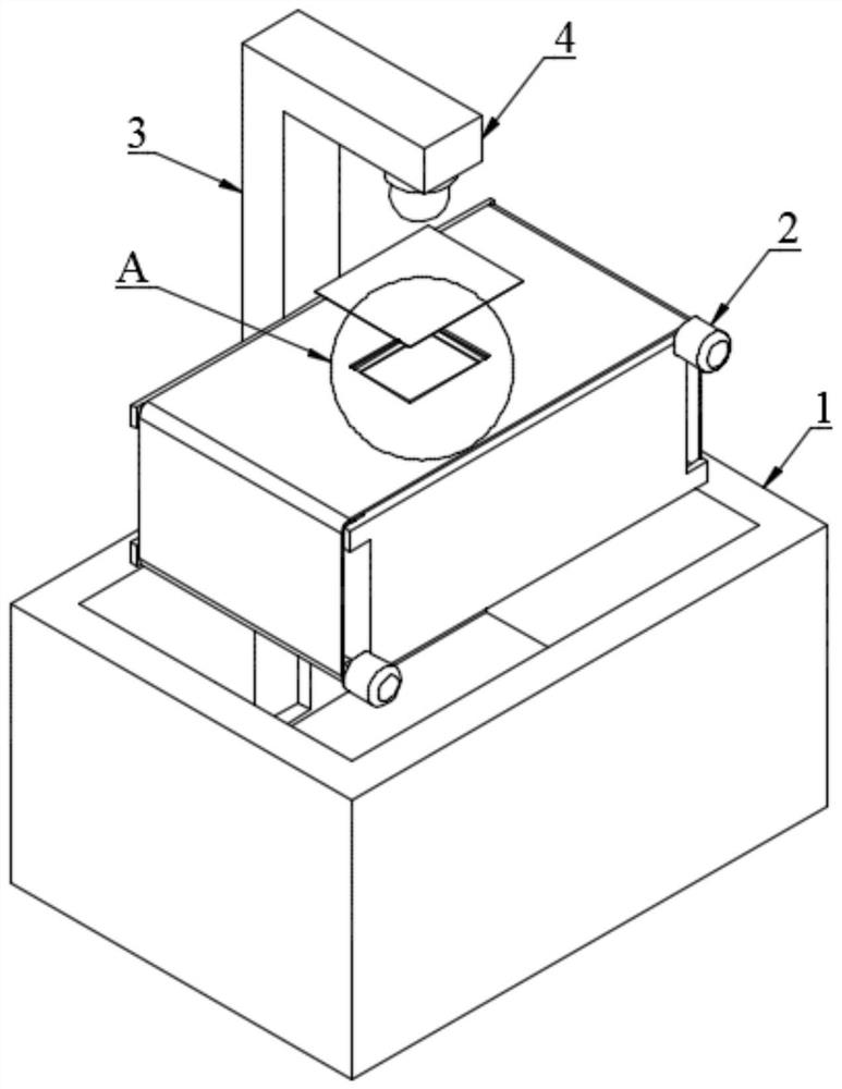
[0061] A computer vision measurement device includes a placement table 1, a background moving component 2, a support frame 3, an image acquisition component and an image processing component.

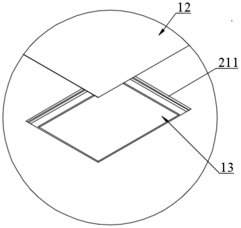
[0062] Such as figure 1 , figure 2 and Figure 5 It can be seen that the placement table 1 includes a placement surface 11 , a carrier 12 located on the placement surface 11 and a groove 13 corresponding to the carrier 12 , the bottom of the groove 13 is provided with a magnetic change component 14 that can exhibit different polarities.

[0063] Such as Figure 5 As shown, the stage 12 includes a flat magnet 121 arranged in the middle of the bottom near the groove 13, a flat plate-shaped pressing plate 122 extending outward on four sides of the top, and a first stepped surface facing inward on the four sides of the bottom. 123 . On the side of the flat magnet 121 away from the magnetic chang...

Embodiment 2

[0076] Please refer to Figure 1 to Figure 6 , the second embodiment of the present invention is:

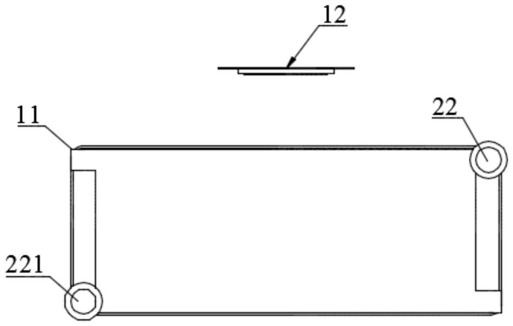
[0077] A computer vision measurement device, on the basis of the first embodiment above, the placing table 1 is further provided with at least one second rotating shaft 223 between the two sides of one of the two sides of the rotating path of the flexible member, And a third rotating shaft 224 corresponding to the number position of the second rotating shaft 223 is provided at a position close to the other side, and the flexible member sequentially passes through the first rotating shaft 222 on the upper side on the side where the second rotating shaft 223 is provided, The second rotating shaft 223 located in between, the third rotating shaft 224 located near the other side, and the first rotating shaft 222 located below form a zigzag structure.

[0078] Therefore, in this embodiment, four placement backgrounds 21 can be placed, and more placement backgrounds 21 can be placed b...

Embodiment 3

[0079] Please refer to Figure 1 to Figure 5 as well as Figure 7 to Figure 9 , Embodiment three of the present invention is:

[0080] A computer vision measuring device, on the basis of the first embodiment above, the annular electromagnet 141 is a strong magnet, at this time, a magnetic isolation material can be arranged around and at the bottom of the strong magnet, so that it only generates magnetic force upward.

[0081] In this embodiment, a turntable 5 , a turn bar 6 , a splicing plate 7 and a second motor 8 are also included. Wherein the output shaft of the second motor 8 is connected to the bottom of the turntable 5, the turntable 5 is provided with a guide groove 51 from the inside to the outside, and the four splicing plates 7 are diagonally spliced ​​into a rectangle matching the bottom of the groove 13, each The bottom of each splicing plate 7 is connected with one end of a rotating rod 6 , and the other end of the rotating rod 6 is located in the guide groove 5...


PUM

PropertyMeasurementUnit
thicknessaaaaaaaaaa

Abstract

The invention discloses a computer vision measurement device, which comprises a placement table, a background moving assembly, a support frame, an image acquisition assembly and an image processing assembly, the placement table comprises a placing surface, a carrying table located on the placing surface and a groove corresponding to the carrying table, magnetic change assemblies capable of presenting different polarities are arranged at the bottom of the groove, a flat plate magnet is arranged at the bottom, close to the groove, of the carrying table, and the side, facing the groove, of the flat plate magnet is of a single polarity; the carrying table is suspended above the placing surface when the magnetic change assembly and the flat magnet have the same polarity; the background moving assembly comprises a thin-layer-shaped flexible part and a rotating part which abuts against the back face of the flexible part so as to drive the flexible part to rotate. The image acquisition assembly is fixed to the upper portion of the containing table through a supporting frame and is aligned to the carrying table. The image acquisition assembly is electrically connected with the image processing assembly. According to the invention, by providing a background with higher contrast, the image acquisition assembly can obtain a high-quality processable image so as to improve the machine vision measurement precision.

Description

technical field [0001] The invention relates to the technical field of machine vision, in particular to a computer vision measuring device. Background technique [0002] Machine vision system is to use machines instead of human eyes to make various measurements and judgments. It is an important branch of computer science, which integrates technologies in optics, mechanics, electronics, computer software and hardware, etc. . The rapid development of technologies such as image processing and pattern recognition has also greatly promoted the development of machine vision. [0003] In machine vision systems, obtaining a high-quality processable image is crucial. According to the existing practical experience, the measurement accuracy of many machine vision measurement devices is prone to deviation, most of which are caused by the inconspicuous features to be measured due to poor image quality. Especially in the case of a variety of items to be tested, different items to be t...

Claims


Application Information

Patent Timeline
Patent Type & Authority Applications(China)
IPC IPC(8): G01N21/84G01N21/01
CPCG01N21/84G01N21/01G01N2021/8466
Inventor 林胜青林薇李婷郑劲松张璜高峰林宇辉孙桂煌鲍国彬陈剑波杨海杰郑佳祥
Owner FUZHOU STRAIT VOCATIONAL & TECH COLLEGE
Why Eureka
Try Eureka