
Flat panel detector pixel structure and manufacturing method thereof

A flat-panel detector and pixel structure technology, which is applied in the direction of electric solid-state devices, semiconductor devices, radiation control devices, etc., can solve the problems of difficult operation of pixels, sharp increase of leakage current of flat-panel detector pixels, and unstable working performance, so as to avoid edge Discharge, reduce surface leakage, eliminate the effect of discharge

Pending Publication Date: 2021-10-22
BEIJING BOE SENSOR TECH CO LTD +1
View PDF0 Cites 0 Cited by
  • Summary
  • Abstract
  • Description
  • Claims
  • Application Information

AI Technical Summary

Problems solved by technology

Although there are currently some products that can work under negative bias voltage, the working performance is not stable enough; as the negative bias voltage increases, the leakage current of flat panel detector pixels will increase sharply
[0003] Therefore, it is difficult for the current flat panel detector pixels to work stably under high negative bias voltage

Method used


Image

  • Flat panel detector pixel structure and manufacturing method thereof
  • Flat panel detector pixel structure and manufacturing method thereof
  • Flat panel detector pixel structure and manufacturing method thereof

Examples


Embodiment Construction

[0045] Hereinafter, embodiments of the present disclosure will be described with reference to the drawings. It should be understood, however, that these descriptions are exemplary only, and are not intended to limit the scope of the present disclosure. Also, in the following description, descriptions of well-known structures and techniques are omitted to avoid unnecessarily obscuring the concept of the present disclosure.

[0046] Various structural schematic diagrams according to embodiments of the present disclosure are shown in the accompanying drawings. The figures are not drawn to scale, with certain details exaggerated and possibly omitted for clarity of presentation. The shapes of the various regions and layers shown in the figure, as well as their relative sizes and positional relationships are only exemplary, and may deviate due to manufacturing tolerances or technical limitations in practice, and those skilled in the art will Regions / layers with different shapes, s...


PUM


Abstract

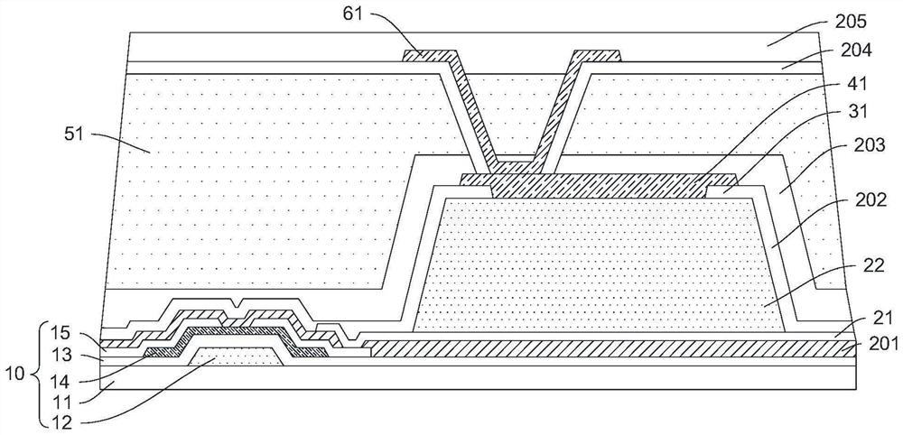
The embodiment of the invention discloses a flat panel detector pixel structure. The flat panel detector pixel structure comprises a PIN film layer; a bottom electrode layer which is arranged on one side of the PIN film layer; an isolation structure which is arranged on the side, far away from the bottom electrode layer, of the PIN film layer; and a top electrode layer which is arranged on the side, away from the PIN film layer, of the isolation structure, the middle of the top electrode layer being connected with the PIN film layer. The orthographic projection of the edge of the top electrode layer on the PIN film layer is covered by the isolation structure. According to the invention, the isolation structure can isolate and insulate the edge of the top electrode layer from the edge and the side wall of the PIN film layer, and can effectively eliminate the discharge effect of the top electrode layer on the side wall of the PIN film layer; and moreover, when the negative bias voltage is increased, the isolation structure can effectively prevent a discharge phenomenon when the current is directly enriched at the metal edge of the top electrode layer, thereby effectively reducing the leakage current of the side wall of the PIN film layer, and enabling the pixels of the flat panel detector to stably work at a higher negative bias voltage.

Description

technical field [0001] The invention relates to the technical field of semiconductor devices, in particular to a flat panel detector pixel structure and a manufacturing method thereof. Background technique [0002] At present, flat-panel detectors are widely used in medical imaging, industrial non-destructive testing, security inspection and other fields. The size can reach tens of centimeters, and the pixel substrate can be composed of millions or even tens of millions of pixel unit circuits. In different application fields, different requirements are often put forward for the performance of flat panel detectors. For example, in some application scenarios, flat panel detectors are required to work under a relatively high negative bias voltage. Although there are currently some products that can work under negative bias voltage, the working performance is not stable enough; as the negative bias voltage increases, the leakage current of the flat panel detector pixel will inc...

Claims


Application Information

Patent Timeline
Patent Type & Authority Applications(China)
IPC IPC(8): H01L27/146
CPCH01L27/14605H01L27/1463H01L27/14643H01L27/14612H01L27/14683
Inventor 王振宇周琳丁志
Owner BEIJING BOE SENSOR TECH CO LTD
Learn More