
High-capacity power transmission method and power transmission system thereof

A power transmission system and large-capacity technology, applied in the direction of electric transmission signal system, system integration technology, information technology support system, etc., can solve problems such as damage to high-voltage transmission towers, inability to rationally deploy power, and inability to understand damage in time. Avoid the effect of damage

Pending Publication Date: 2021-10-22
韩秋华
View PDF0 Cites 1 Cited by
  • Summary
  • Abstract
  • Description
  • Claims
  • Application Information

AI Technical Summary

Problems solved by technology

[0005] The present invention provides a large-capacity electric power transmission method and its electric power transmission system, one purpose of which is to have the power load in different regions, so as to make a reasonable distribution of power, and solve the problem that the power cannot be distributed according to the different power loads. The problem of making reasonable deployment; another purpose is to solve the problem of not knowing the damage in time when the high-voltage transmission tower is damaged due to natural reasons, so as to quickly understand the damage of the damaged high-voltage transmission tower Effect

Method used

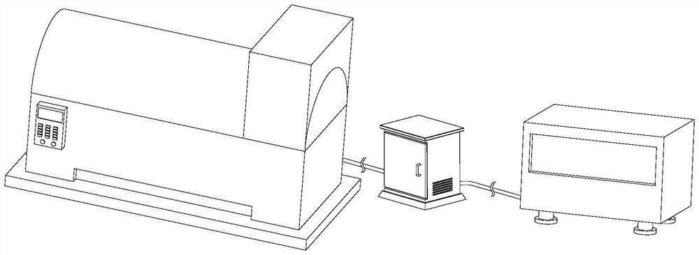

Image

  • High-capacity power transmission method and power transmission system thereof
  • High-capacity power transmission method and power transmission system thereof
  • High-capacity power transmission method and power transmission system thereof

Examples


Embodiment 1

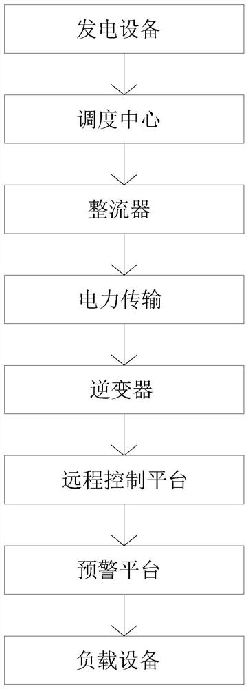
[0051] First aspect, such as Figure 1-8 As shown, the present invention provides a large-capacity power transmission system, including power generation equipment, dispatching center, rectifier, power transmission, inverter, remote control platform, early warning platform and load equipment, and the specific uses of each component are:

[0052] The power generation equipment generates power through the equipment;

[0053] The dispatch center conducts dispatch through the electricity consumption in different regions;

[0054] The rectifier converts alternating current to direct current by pairing;

[0055] Power transmission transmits power through high-voltage transmission towers to reduce power loss during transmission;

[0056]The inverter converts the transmitted direct current into alternating current;

[0057] The remote control platform monitors and protects the transmitted power;

[0058] The early warning platform is monitored through the transmission tower of the ...


PUM


Abstract

The invention discloses a high-capacity power transmission method and a high-capacity power transmission system, and relates to the technical field of power transmission, and the high-capacity power transmission system comprises power generation equipment, a dispatching center, a rectifier, power transmission, an inverter, a remote control platform, an early warning platform and load equipment. Thepower generation equipment generates power through devices; the dispatching center carries out dispatching through power loads of different regions, the rectifier converts generated alternating current into direct current, power transmission is carried out through the high-voltage line transmission tower, and therefore loss of the power in the transmission process is reduced. According to the invention, the power can be allocated more reasonably according to the electrical loads of different regions through the dispatching center, so that the situation of insufficient power in some regions with large electrical loads is avoided, the situation of excessive power in some regions with small electrical loads is also avoided, the situation of uneven power distribution is avoided, and the power utilization efficiency is improved. and the electric power can be fully utilized.

Description

technical field [0001] The invention relates to the technical field of power transmission, in particular to a large-capacity power transmission method and a power transmission system thereof. Background technique [0002] Electric energy transmission refers to a way that a power plant or power supply is transmitted from one place to another. Due to the immature technology in the early stage, DC transmission was mostly used for electric energy transmission, and later it gradually evolved into AC transmission. AC transmission has many advantages and reduces power consumption. The loss in transmission increases the speed and transmission length. The power system is an electric energy production and consumption system composed of power generation, power transformation, power transmission, power distribution and power consumption. Its function is to use the primary energy of nature through power generation. The device converts electrical energy, and then supplies the electrical e...

Claims


Application Information

Patent Timeline
Patent Type & Authority Applications(China)
IPC IPC(8): H02J3/46H02J13/00G08B7/06
CPCH02J3/466H02J13/00002G08B7/06Y02E40/70Y04S10/12Y04S10/50
Inventor 韩秋华
Owner 韩秋华
Learn More