Positioning mechanism of air sensor press-fitting equipment

An air sensor and positioning mechanism technology, which is applied to workpiece clamping devices, workbenches, manufacturing tools, etc., can solve the problems of small application range of positioning mechanism, low tooling efficiency, inconvenient adjustment and use for different groups of people, etc. Simple, easy to operate, and the effect of increasing stability

Pending Publication Date: 2021-10-26
广东顺德正综科技服务有限公司
View PDF8 Cites 2 Cited by
  • Summary
  • Abstract
  • Description
  • Claims
  • Application Information

AI Technical Summary

Problems solved by technology

[0004] The purpose of the present invention is to solve the shortcomings of the existing positioning mechanism, which are mostly manually positioned and clamped, the efficiency of the tooling is low, and the scope of application of the positioning mechanism is small, it is not easy to adjust and use for different groups of people, and a kind of air sensor is proposed. Positioning mechanism of press-fitting equipment

Method used


Image

  • Positioning mechanism of air sensor press-fitting equipment
  • Positioning mechanism of air sensor press-fitting equipment
  • Positioning mechanism of air sensor press-fitting equipment

Examples


Embodiment 1

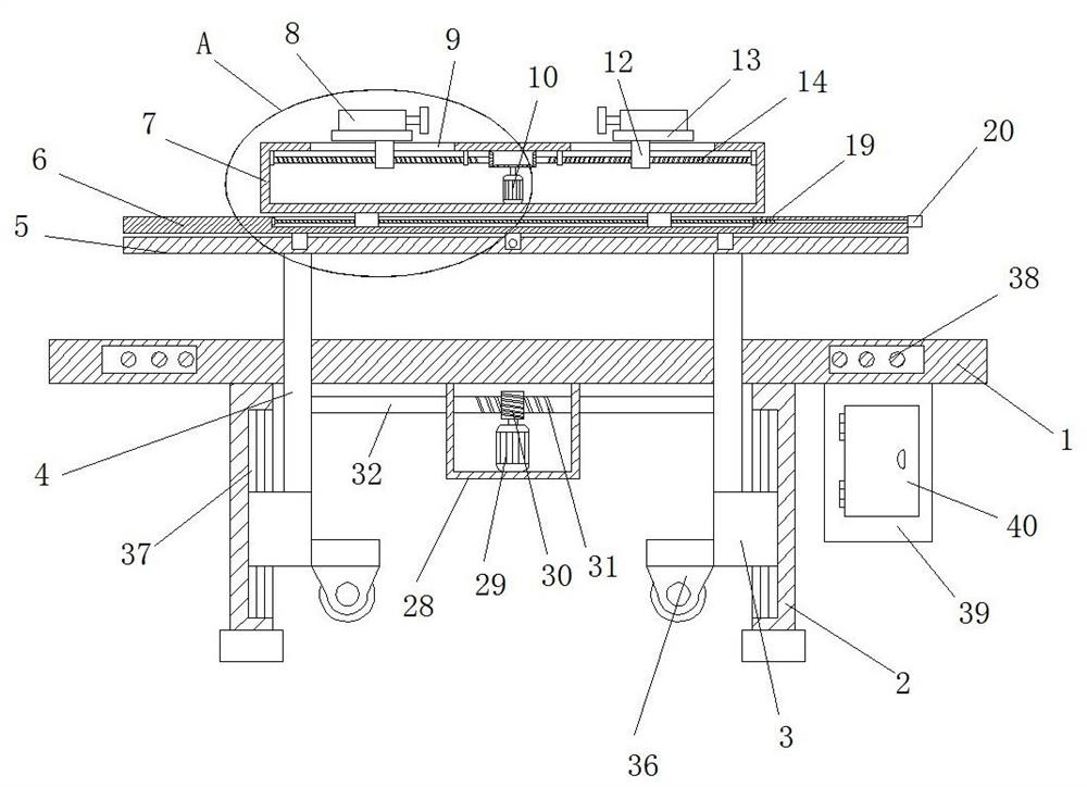
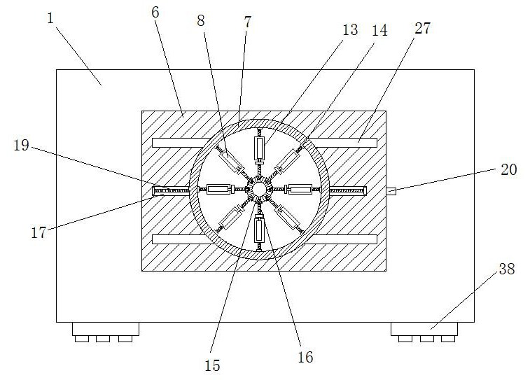
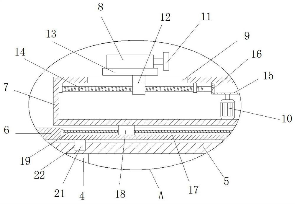
[0030] refer to Figure 1-5 , a positioning mechanism of an air sensor press-fitting equipment, including a work plate 1, four support legs 2 are fixedly installed at the bottom of the work plate 1, and slide blocks 3 are slidably installed on the four support legs 2, and the four slide blocks 3 A universal wheel 36 is fixedly connected on one side of the working plate 1, and two lifting plates 4 are vertically slidably installed on the top of the working plate 1. The bottom is provided with a lift drive mechanism, the two lift plates 4 are adapted to the lift drive mechanism, the tops of the two lift plates 4 are fixedly installed with a longitudinal support plate 5, and the top of the longitudinal support plate 5 is provided with a longitudinal drive mechanism. A lateral support plate 6 is installed on the drive mechanism, a lateral drive mechanism is arranged on the top of the lateral support plate 6, a positioning box 7 is installed on the lateral drive mechanism, and the ...

Embodiment 2

[0041] refer to Figure 1-5 , a positioning mechanism for air sensor press-fitting equipment, including a working board 1, four supporting legs 2 are fixedly installed on the bottom of the working board 1 by welding, sliding blocks 3 are installed on the four supporting legs 2, and four sliding One side of block 3 is fixedly connected with universal wheel 36 by screws, and the top of working plate 1 is vertically slid to install two lifting plates 4, and the two lifting plates 4 are respectively fixed to the tops of the corresponding two sliding blocks 3 by welding Installation, the bottom of the working board 1 is provided with a lifting drive mechanism, and the two lifting plates 4 are compatible with the lifting drive mechanism, and the tops of the two lifting plates 4 are fixedly installed with a longitudinal support plate 5 by welding, and the longitudinal support plate 5 The top is provided with a longitudinal driving mechanism, and a horizontal support plate 6 is instal...


PUM


Abstract

The invention belongs to the technical field of workpiece positioning, particularly relates to a positioning mechanism of air sensor press-fitting equipment, and provides the following scheme to solve the problems that existing positioning mechanisms mostly perform positioning and clamping manually, the tool efficiency is low, the application range of the positioning mechanisms is small, adjustment is inconvenient, and the positioning mechanisms cannot be conveniently used for different crowds. The positioning mechanism comprises a working plate, four supporting legs are fixedly installed at the bottom of the working plate, sliding blocks are installed on the four supporting legs in a sliding mode, universal wheels are fixedly connected to the sides of the four sliding blocks, two lifting plates are vertically installed at the top of the working plate in a sliding mode, the two lifting plates and the tops of the two corresponding sliding blocks are fixedly installed, and a lifting driving mechanism is arranged at the bottom of the working plate. The positioning mechanism is simple in structure and convenient to operate, workpieces can be automatically clamped and positioned, the tool efficiency is improved, the position of the positioning mechanism can be adjusted, the positioning device can be used for different crowds, and the application range is widened.

Description

technical field [0001] The invention relates to the technical field of workpiece positioning, in particular to a positioning mechanism of an air sensor press-fitting device. Background technique [0002] In mechanical processing, it is usually necessary to position the workpiece and then press-fit. At present, the assembly of air sensors still has the defects of manual positioning and clamping. The manual positioning and clamping process is complicated, the degree of automation is low, the scope of use is small, and the control performance is low. . [0003] The existing positioning mechanism mostly performs positioning and clamping manually, which has low tooling efficiency, and the positioning mechanism has a small scope of application, which is inconvenient to adjust and use for different groups of people. SUMMARY OF THE INVENTION [0004] The purpose of the present invention is to solve the shortcomings of the existing positioning mechanism that is mostly manually pos...

Claims


Application Information

Patent Timeline
Patent Type & Authority Applications(China)
IPC IPC(8): B25H1/10B25B11/02
CPCB25H1/10B25B11/02
Inventor 周长春周树驿陈珍梅
Owner 广东顺德正综科技服务有限公司
Why Eureka
Try Eureka