Decorative ceramic tile cutting and positioning device

A positioning device and ceramic tile technology, which is applied in the direction of stone processing tools, work accessories, springs/shock absorbers, etc., can solve the problems of increasing the work intensity of the staff and low work efficiency, so as to reduce labor intensity, increase cutting speed, and ensure The effect of cut quality

Active Publication Date: 2021-10-26
阿郎装饰股份有限公司
View PDF6 Cites 2 Cited by
  • Summary
  • Abstract
  • Description
  • Claims
  • Application Information

AI Technical Summary

Problems solved by technology

[0003]The existing cutting device can only cut the tiles on the same straight line, but sometimes it is necessary to cut the tiles in different directions when laying the tiles, so it is necessary to The staff rem

Method used


Image

  • Decorative ceramic tile cutting and positioning device
  • Decorative ceramic tile cutting and positioning device
  • Decorative ceramic tile cutting and positioning device

Examples


Embodiment 2

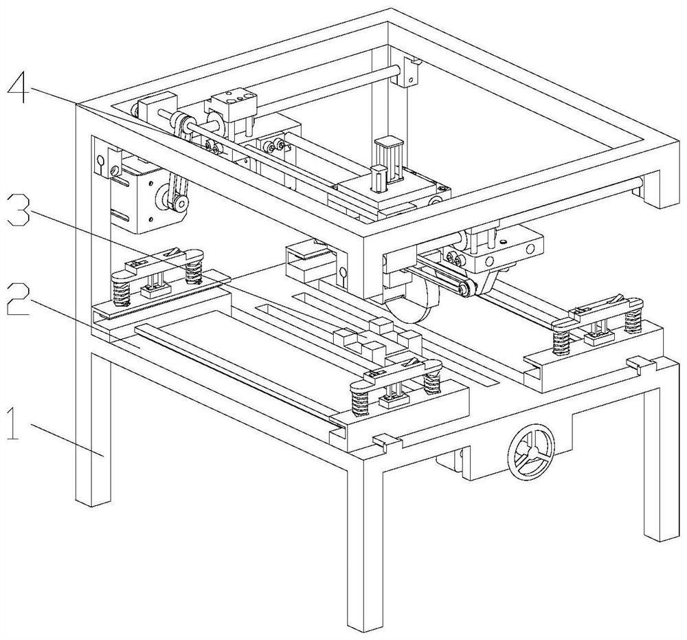
[0050] The difference from Embodiment 1 is that a guide rail 5 and a positioning mechanism 6 matched with the guide rail 5 are also installed on the placement frame 2. The positioning mechanism 6 is installed in the chute 9 and symmetrically installed at the bottom of the placement frame 2. There is a mounting plate 8, and the positioning mechanism 6 includes a positioning clamp 605, a connecting plate 604, a second threaded rod 603, a handle 602 and a slide bar 601, and the guide rail 5 is provided with two, and the two guide rails 5 are symmetrically installed on the placement frame 2, the positioning clips 605 are in one-to-one correspondence with the guide rails 5, and there is a guide groove 606 at the bottom of the positioning clip 605, the guide grooves 606 match the guide rails 5, and the connecting plate 604 is located at the bottom of the placement frame 2 , and the two ends of the connecting plate 604 pass through the chute 9 to connect with the positioning clip 605,...

Embodiment 3

[0054] The difference from Embodiment 1 and Embodiment 2 is that a fixing mechanism 7 is installed on the positioning clip 605, and the fixing mechanism 7 includes a fixing seat 701, a support plate 702, a fixing column 704, a first spring 703, a second spring 705. The connecting rod 706 has an installation hole in the middle of the support plate 702. The inside of the installation hole is provided with a connecting rod 706 and a second spring 705. The connecting rod 706 includes an inclined part and a vertical part, and the connecting rod 706 The connection between the inclined part and the vertical part of the second spring 705 is installed on the support plate 702 through the rotation of the rotating shaft. One end of the second spring 705 is installed on the support plate 702, and the other end is installed on the bottom of the inclined part of the connecting rod 706. When the connecting rod 706 is vertical The bottom of the part is equipped with a limit block 707, the fixe...

Embodiment 4

[0057] The difference from Embodiment 1, Embodiment 2, and Embodiment 3 is that the fixing mechanism 7 also includes a third spring 709 and a clamping plate 708, one end of the third spring 709 is installed on the fixing column 704, and the other One end is installed on the clamping plate 708, and the clamping plate 708 is arranged in the positioning clamp 605, and the third spring 709 acts as a buffer, and can also provide pre-tightening force for the clamping plate 708, and continuously clamp the tiles. The setting of the clamping plate 708 is convenient to spread the pressure on the fixing column 704 to apply on the ceramic tiles, so as to prevent damage to the ceramic tiles caused by excessive force at a single point.


PUM


Abstract

The invention discloses a decorative ceramic tile cutting and positioning device. The decorative ceramic tile cutting and positioning device comprises a rack, a walking mechanism and a placing frame are installed on the rack, the walking mechanism is installed on the top of the rack, the placing frame is installed below the walking mechanism, and the walking mechanism comprises a transverse moving mechanism and a longitudinal moving mechanism. The longitudinal moving mechanism is installed on the transverse moving mechanism, and a cutting mechanism is installed on the longitudinal moving mechanism. According to the decorative ceramic tile cutting and positioning device, ceramic tiles can be cut in different directions, the labor intensity of workers is reduced, the transverse moving mechanism can drive the cutting mechanism to transversely move to achieve the purpose of transversely cutting the ceramic tiles, and the longitudinal moving mechanism can drive the cutting mechanism to longitudinally move to achieve the purpose of longitudinally cutting the ceramic tiles; and the cutting speed of the ceramic tiles is greatly improved.

Description

technical field [0001] The invention belongs to the technical field of decoration, in particular to a cutting and positioning device for decorative ceramic tiles. Background technique [0002] Ceramic tiles are refractory metal oxides and semi-metal oxides, which are formed through the process of grinding, mixing, pressing, glazing and sintering, and are an acid and alkali resistant porcelain or stone construction or decoration material. It is generally called ceramic tiles, and its raw materials are mostly mixed with clay, quartz sand, etc. Ceramic tiles are used in a wide range, especially in architectural decoration, and the usage rate of ceramic tiles is higher. And there are fixed specifications and sizes, but the area of ​​the wall and the floor where the tiles are laid cannot be an integer multiple of the area of ​​the tiles, so workers need to cut the tiles when laying. [0003] The existing cutting device can only cut the tiles on the same straight line, but someti...

Claims


Application Information

Patent Timeline
IPC IPC(8): B28D1/24B28D7/00B28D7/04F16F15/067
CPCB28D1/24B28D7/00B28D7/04F16F15/067
Inventor 肖楷文付纳丰刘延良
Owner 阿郎装饰股份有限公司
Why Eureka
Try Eureka