Anti-icing hydraulic engineering gate
A technology for water conservancy projects and gates, which is applied in the field of anti-icing water conservancy project gates. It can solve the problems of increased gap between the gate frame and the gate, excessive friction between the gate frame and the gate, and easy icing of the gate, so as to avoid heat loss and avoid Icing, easy lifting effect
- Summary
- Abstract
- Description
- Claims
- Application Information
AI Technical Summary
Problems solved by technology
Method used
Image
Examples
Embodiment 1
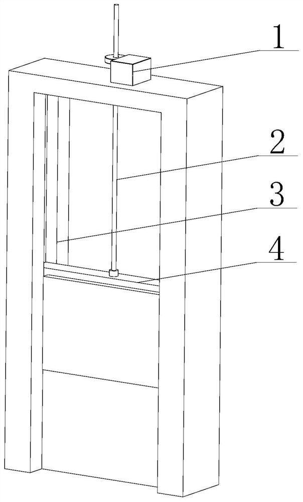
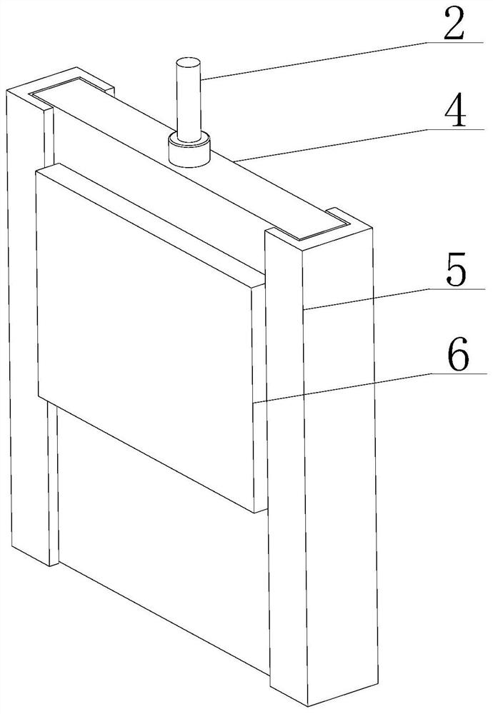
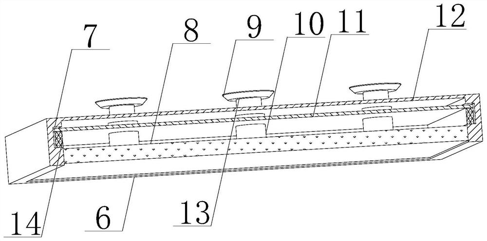
[0040] Such as Figure 1-4As shown, the present invention provides a gate for anti-icing water conservancy projects, including a lifting mechanism 1, a lifting rod 2, a gate frame 3 and a gate main body 4, the inner wall of the gate frame 3 is slidingly connected with a gate main body 4, and the top of the gate main body 4 is arranged There is a lifting rod 2, the top of the lifting rod 2 runs through the top of the gate frame 3, the outer wall of the lifting rod 2 and the top of the gate frame 3 are provided with a lifting mechanism 1, and the front of the gate main body 4 is fixedly installed with an ice-insulating mounting plate 6. The back side of the ice installation plate 6 is provided with a placement groove 12, and the edge of the placement groove 12 is fixedly equipped with a cavity plate 8. A scraper frame 5 is installed, and the outer wall of the scraper frame 5 is slidingly connected with the inner wall of the gate frame 3. The inner wall of the placement groove 12...
Embodiment 2
[0042] Such as Figure 1-4 As shown, on the basis of Embodiment 1, the present invention provides a technical solution: preferably, the top of the inner wall of the cavity plate 8 is fixedly connected with a positioning installation column 17, and the other end of the positioning installation column 17 is fixedly connected with a hollow heating plate 15. The bottom of the inner wall of the hollow heating plate 15 is fixedly connected with a temperature-conducting sticker 16, and the positioning mounting columns 17 are symmetrically arranged on both sides of the hollow heating plate 15, and the top of the hollow heating plate 15 is attached to the inner wall of the cavity plate 8. The positioning mounting column 17 is convenient for the hollow heating plate 15 to be installed and fixed. At the same time, the hollow heating plate 15 can transfer heat quickly. The plate 16 can increase the temperature of the gate main body 4, thereby preventing the gate main body 4 from freezing ...
Embodiment 3
[0044] Such as Figure 1-4 As shown, on the basis of Embodiment 1, the present invention provides a technical solution: preferably, the side of the scraper frame 5 is provided with a storage card slot 19, and the inner wall of the storage card slot 19 is hinged with a movable scraper 20, and the movable scraper The bottom of plate 20 is fixedly connected with resetting elastic plate 21, and the other end of resetting elastic plate 21 is fixedly connected with the inwall of receiving draw-in groove 19, and the inner wall bottom of receiving draw-in groove 19 is fixedly connected with elastic member 22, and the top of elastic member 22 and movable The bottom of cleaning plate 18 is fixedly connected, and elastic member 22 makes movable cleaning plate 18 reset movable cleaning plate 18 in the process of scraping off, thereby facilitating movable cleaning plate 18 to repeatedly scrape off, while movable cleaning plate 18 can be according to According to the actual situation of the...
PUM
 Abstract
Description
Claims
Application Information
 - R&D
- Intellectual Property
- Life Sciences
- Materials
- Tech Scout
- Unparalleled Data Quality
- Higher Quality Content
- 60% Fewer Hallucinations
Browse by: Latest US Patents, China's latest patents, Technical Efficacy Thesaurus, Application Domain, Technology Topic, Popular Technical Reports.
© 2025 PatSnap. All rights reserved.Legal|Privacy policy|Modern Slavery Act Transparency Statement|Sitemap|About US| Contact US: help@patsnap.com


