Water energy power generation circulating device for water energy generator set
A technology of generator set and circulation device, which is applied in the directions of hydropower generation, engine components, machines/engines, etc., can solve the problems of insufficient power supply affecting domestic electricity consumption, etc., and achieve the effects of increasing practicability, preventing relative motion, and reducing noise.
- Summary
- Abstract
- Description
- Claims
- Application Information
AI Technical Summary
Problems solved by technology
Method used
Image

Examples
Embodiment 1
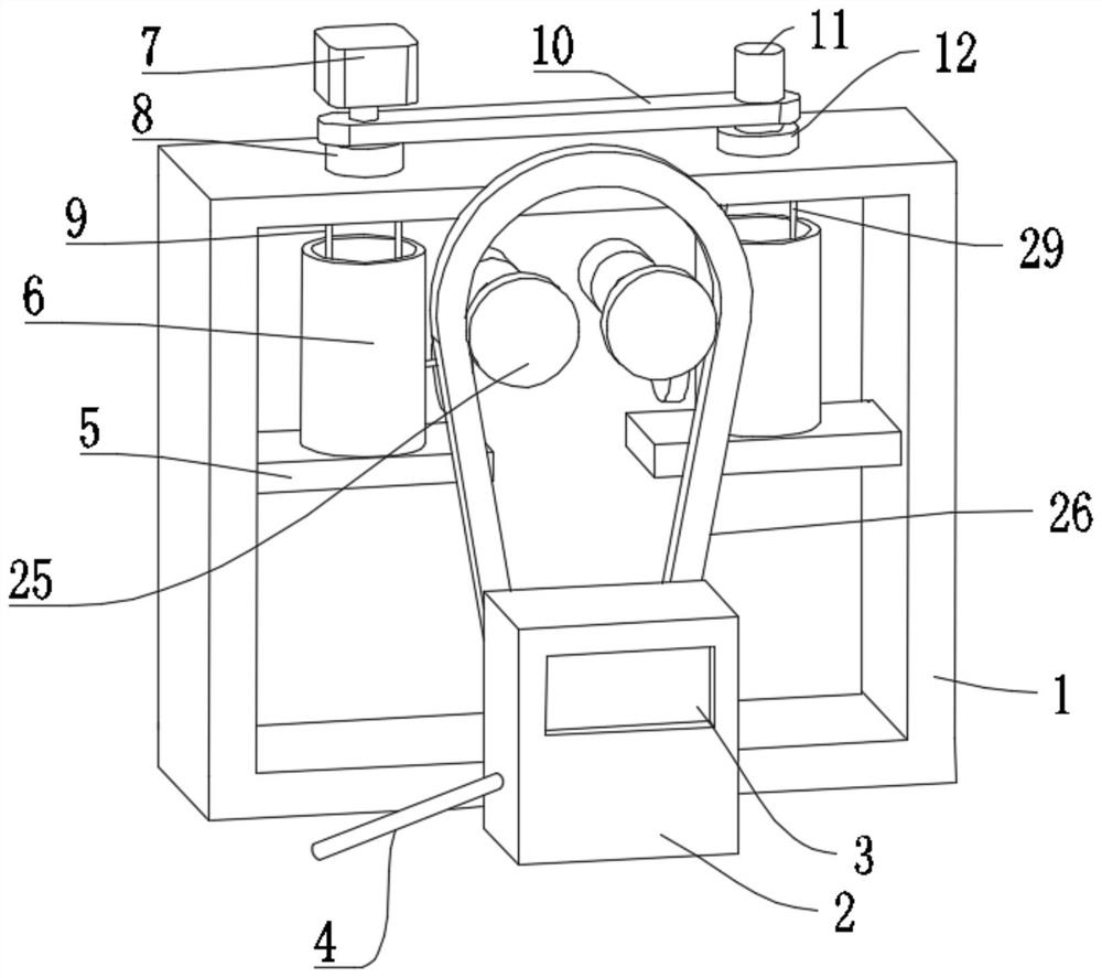
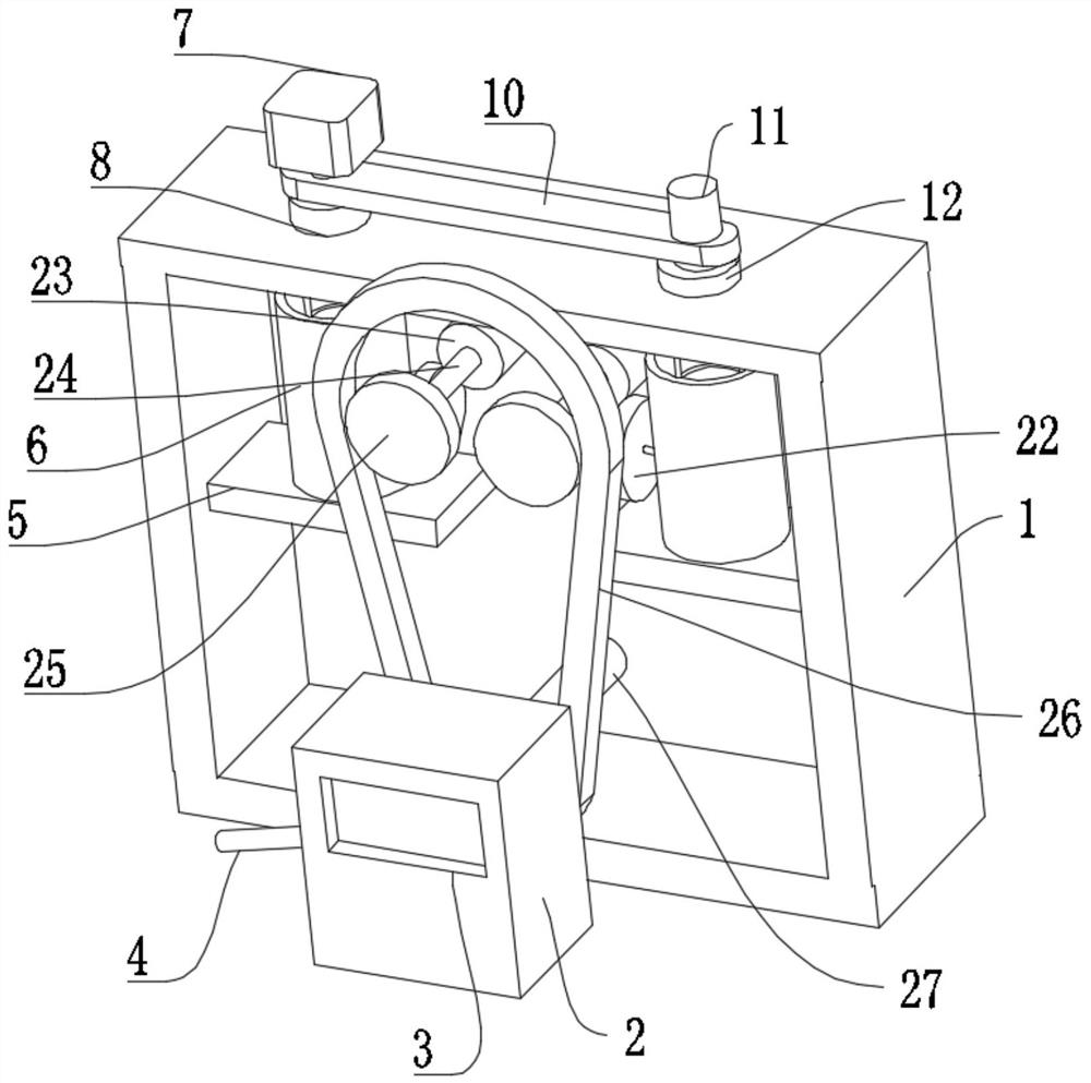
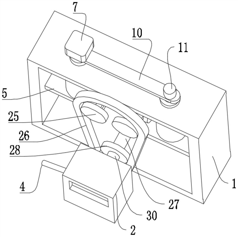
[0031] Such as figure 1 , figure 2 , image 3 , Figure 6 and Figure 7 As shown, a water energy power generation circulation device for a hydropower generator set proposed by the present invention includes a casing 1 and a generator set 2 fixedly arranged on the outside of the casing 1. A power generation cycle mechanism is arranged inside the casing 1, and the power generation cycle mechanism includes The two mounting plates 5 fixedly arranged in the housing 1 are fixedly provided with water storage barrels 6 on the two mounting plates 5, and the inner walls of the two water storage barrels 6 are provided with cylindrical rods 21 through bearing rotation, and the two cylindrical rods 21 One end close to the center of the housing 1 runs through the water storage bucket 6 and extends to the outside of the water storage bucket 6, and the end faces of the two cylindrical rods 21 are fixed with bevel gears A22, and the same linkage assembly is set on the two bevel gears A22 ...
Embodiment 2
[0038] Such as figure 1 , Figure 6 , Figure 7 and Figure 8 Shown, based on the basis of embodiment 1, the two water circulation components all include the drainage bucket 13 separated from the bottom wall of the water storage bucket 6, the upper parts of the two drainage buckets 13 are provided with a plurality of holes 14, and the two cylindrical rods 21 The two impeller parts 31 are fixedly arranged on the top, and the two impeller parts 31 are located in the water storage bucket 6 and below the drainage bucket 13, and the top of one of the drainage buckets 13 is fixedly equipped with a connecting rod A9, and the top of the housing 1 is rotatably connected by a bearing. There is a turntable A8, the top of the turntable A8 is fixedly provided with a motor 7 connected by a motor base, and the top of the connecting rod A9 penetrates through the housing 1 and is fixedly connected to the bottom of the turntable A8;
[0039] The top of the housing 1 is rotatably connected wi...
Embodiment 3
[0042] Such as Figure 4 , Figure 5 and Figure 7 As shown, based on the above embodiment 1 or 2, the impeller component 31 includes a wheel disc 15 fixedly connected with the cylindrical rod 21, the side wall of the wheel disc 15 is provided with a groove 19, and the front and rear end surfaces of the wheel disc 15 are provided with a slot 18, and the recessed The movable blade 16 is arranged in the groove 19, and the two sides of the movable blade 16 are fixed with elastic protrusions 17, and the protrusions 17 are matched with the slots 18;
[0043] An anti-skid pad 20 is fixedly arranged on the contact surface between the rotor blade 16 and the wheel disc 15;
[0044] In this embodiment, when assembling the impeller part 31, press and hold the elastic protrusion 17, the protrusion 17 is compressed in the direction of the moving blade 16, and then insert the connecting end of the moving blade 16 into the groove 19, so that the protrusion 17 is inserted In the card slot ...
PUM
 Abstract
Description
Claims
Application Information
 - R&D
- Intellectual Property
- Life Sciences
- Materials
- Tech Scout
- Unparalleled Data Quality
- Higher Quality Content
- 60% Fewer Hallucinations
Browse by: Latest US Patents, China's latest patents, Technical Efficacy Thesaurus, Application Domain, Technology Topic, Popular Technical Reports.
© 2025 PatSnap. All rights reserved.Legal|Privacy policy|Modern Slavery Act Transparency Statement|Sitemap|About US| Contact US: help@patsnap.com