Locking differential mechanism

A differential and locking technology, applied in the direction of differential transmission, belt/chain/gear, mechanical equipment, etc., can solve the problem of loss of traction function, the car cannot have enough traction, etc., to achieve the effect of high locking rate

Pending Publication Date: 2021-10-26
台州市阿瑞诗汽车配件有限公司
View PDF0 Cites 0 Cited by
  • Summary
  • Abstract
  • Description
  • Claims
  • Application Information

AI Technical Summary

Problems solved by technology

Therefore, the drive axle needs to use the differential to distribute the torque transmission to the left and right driving wheels to adapt to the different speed requirements caused by the above factors and achieve the purpose of reducing tire wear when the vehicle is running. However, when the car encounters bad road conditions, one of the If the wheel is suspended in the air or the friction with the ground is reduced, causing the wheel to spin, the other wheel will lose its traction function, and the car will not have enough traction to get out of trouble

Method used


Image

  • Locking differential mechanism
  • Locking differential mechanism

Examples


Embodiment Construction

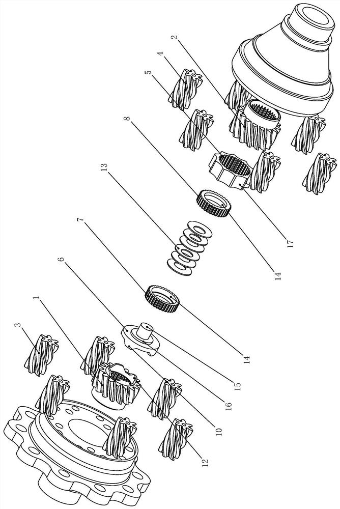
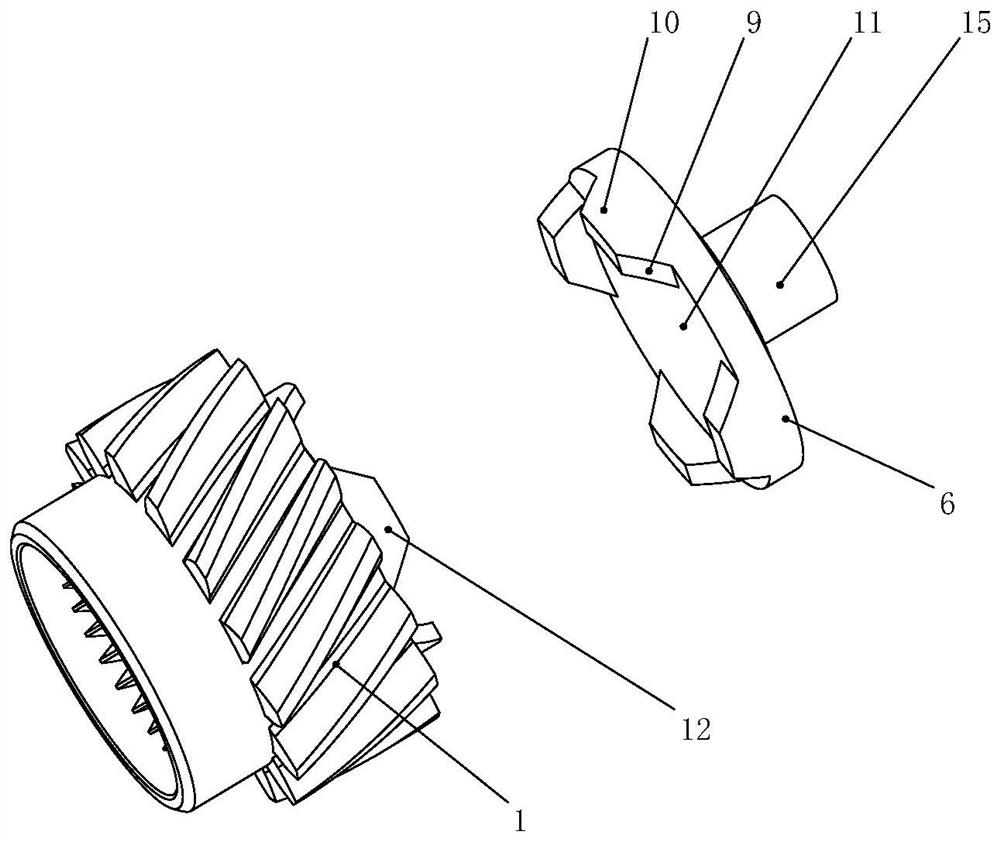
[0017] The present invention will be further described with reference to the specific embodiments. figure 1 -2:

[0018] Differential for a latch A locking differential, comprising a housing, the axle housing rotatably connected to the left helical teeth 1, 2 and right axle helical teeth, the helical teeth meshing with the left axle shaft 1 left planet gears 3, 4 and a right planetary gear, the planetary gear 3 and the left and right planetary gear 4 engaged circumferentially staggered and located between the left and the right axle half shaft 1 helical teeth meshing with the helical teeth of the helical teeth of the right axle 2 between the housing 2 equipped with a movable axially and circumferentially of the housing 5 rotate synchronously intermediate ring, the intermediate ring and the left axle shaft 5 is provided with a spiral movable axially between the teeth of a driving seat 6, the intermediate ring 5 on the inner hole of the right friction engagement with the gear 7 is c...


PUM


Abstract

The invention belongs to the technical field of differential mechanisms, and particularly relates to a locking differential mechanism. The locking differential mechanism comprises a shell, left half shaft spiral teeth, right half shaft spiral teeth, a left planetary gear and a right planetary gear are rotationally connected in the shell, a middle check ring is arranged in the shell, a driving seat is arranged between the middle check ring and the left half shaft spiral teeth, the driving seat is in circumferential linkage with the left half shaft spiral teeth through the circumferential driving surface, and when the left half shaft spiral teeth rotate relative to the driving seat in the circumferential direction, the left half shaft spiral teeth can drive the driving seat to move in the axial direction through the circumferential driving surface and push the middle check ring to abut against the right half shaft spiral teeth. When an automobile idles or slips, the left half shaft spiral teeth and the driving seat can rotate relatively, the driving seat pushes the middle check ring to abut against the right half shaft spiral teeth in the axial direction of the driving seat under the guidance of the circumferential driving surface, thus the middle check ring and the driving seat are tightly attached together to form approximately-rigid fixed connection, and enough traction force is provided for the automobile.

Description

Technical field: [0001] The present invention belongs to the technical field differential, in particular to a locking differential. Background technique: [0002] In the traveling of the vehicle, since the road is not flat, the outer diameter of the tire are not the same, different tire pressure and tire wear, wheel load caused by different tires of different loads vary the rolling radius due to other factors, will result in the left and right tires speed is not the same. Thus by means of the differential drive axle need to transmit torque to the right and left driving wheels assigned to accommodate the needs of different speed caused by these factors, with the purpose to reduce vehicle tire wear, but when the vehicle encounters poor road conditions, where a If the wheel vacant or reduce friction with the ground caused by wheel spin, then another one wheel loses traction function, thus making the car can not have enough traction out of trouble. SUMMARY OF THE INVENTION [0003] ...

Claims


Application Information

Patent Timeline
IPC IPC(8): F16H48/06F16H48/22
CPCF16H48/06F16H48/22F16H2048/201
Inventor 林子凯
Owner 台州市阿瑞诗汽车配件有限公司
Why Eureka
Try Eureka