
Nanofiber cable sleeve preparation process

A preparation process and nanofiber technology, applied in the field of cable sleeves, can solve the problems of no automatic cooling, inability to apply evenly, etc.

Inactive Publication Date: 2021-10-26
彭苏梁
View PDF0 Cites 0 Cited by
  • Summary
  • Abstract
  • Description
  • Claims
  • Application Information

AI Technical Summary

Problems solved by technology

[0005] Aiming at the deficiencies of the prior art, the present invention provides a nanofiber cable sheath preparation process, which has the advantages of uniform coating and automatic cooling, and solves the problem that the existing cable sheath preparation equipment cannot be evenly coated and does not have automatic cooling

Method used


Image

  • Nanofiber cable sleeve preparation process
  • Nanofiber cable sleeve preparation process
  • Nanofiber cable sleeve preparation process

Examples


Embodiment 1

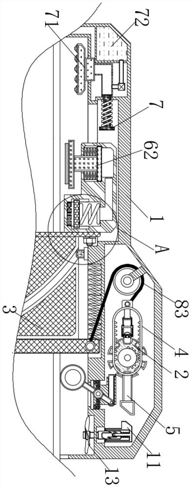
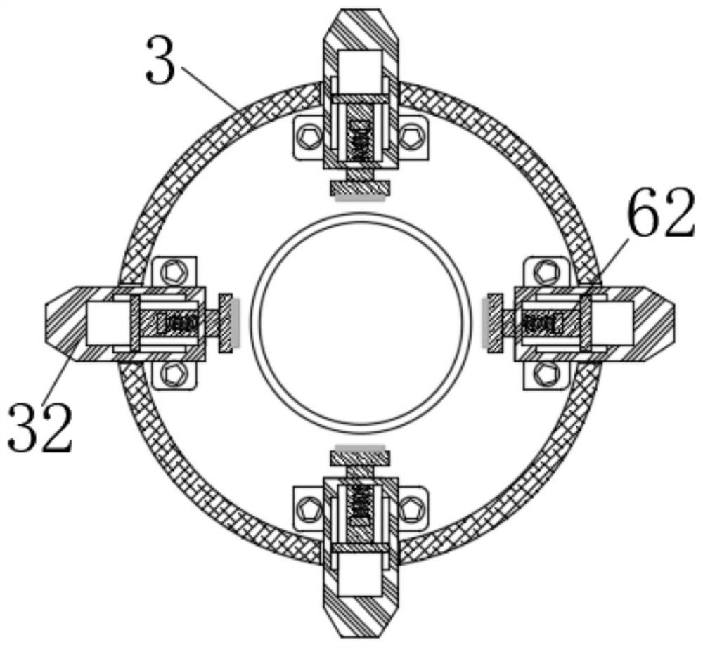
[0026] see Figure 1-3 , a nanofiber cable sleeve preparation process, including a casing 1 and a driving wheel 2, the inside of the casing 1 is slidably connected with a pushing mechanism 3, the upper part of the pushing mechanism 3 is provided with a first block 31, and the left side of the pushing mechanism 3 is fixedly connected with The clamping mechanism 32 is rotatably connected with the intermittent device 4 on the surface of the drive wheel 2 , and the first push rod 5 is fixedly connected with the right end of the intermittent device 4 .

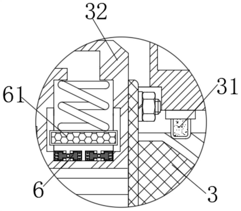
[0027] Further, a notch is opened on the surface of the pushing mechanism 3, and cooperates with the first stopper 31 inside the casing 1, and the electromagnetic device 6 is fixedly connected inside the clamping mechanism 32, and the first magnetic block 61 is arranged on the upper part of the electromagnetic device 6 The magnetic poles of the magnetic field generated by the electromagnetic device 6 are the same as the magnetic po...

Embodiment 2

[0032] see Figure 2-5, a nanofiber cable sleeve preparation process, including a casing 1 and a driving wheel 2, the inside of the casing 1 is slidably connected with a pushing mechanism 3, the upper part of the pushing mechanism 3 is provided with a first block 31, and the left side of the pushing mechanism 3 is fixedly connected with The clamping mechanism 32 is rotatably connected with the intermittent device 4 on the surface of the drive wheel 2 , and the first push rod 5 is fixedly connected with the right end of the intermittent device 4 .

[0033] Further, the bottom of the first push rod 5 is provided with a fixed rod 9, the fixed rod 9 is slidably connected inside the casing 1, and matches with the notch on the surface of the drive wheel 2, the surface of the fixed rod 9 is rotatably connected with a movable rod 10, When the cable enters the inside of the casing 1, the cable drives the fixed rod 9 to slide to the right by squeezing the movable rod 10, so that the fix...


PUM


Abstract

The invention discloses a nanofiber cable sleeve preparation process which comprises a machine shell and a driving wheel, a pushing mechanism is slidably connected into the machine shell, a first stop block is arranged on the upper portion of the pushing mechanism, a clamping mechanism is fixedly connected to the left side of the pushing mechanism, an intermittent device is rotatably connected to the surface of the driving wheel, and a first push rod is fixedly connected to the right end of the intermittent device. According to the preparation technology of the nanofiber cable sleeve, an electromagnetic device repels a first magnetic block to move upwards, so that the first magnetic block drives a pressing rod to slide downwards by extruding air, the clamping mechanism fixes the surface of a cable, and a pushing mechanism drives the cable to rotate in a machine shell; and meanwhile, the pushing mechanism drives the second push rod to slide through the clamping mechanism, and the second push rod drives the nanofiber material to cover the surface of the cable through the coating device, so that the effect that the coating device uniformly coats the surface of the cable with the nanofiber material is achieved through the pushing mechanism and the second push rod.

Description

technical field [0001] The invention relates to the technical field of cable sheaths, in particular to a preparation process of nanofiber cable sheaths. Background technique [0002] With the continuous development of social and economic conditions, cable sleeves have been widely used in the fields of telecommunication construction, electric power engineering or urban construction. The requirements for strength, stiffness or corrosion resistance of cable sheaths are getting higher and higher, so that relevant personnel have developed nanofiber cable sheath materials and related auxiliary devices according to the requirements to solve the problem. [0003] At present, there are many kinds of nanofiber cable sheath laying devices on the market, which generally cannot be applied evenly. When the nanofiber material is applied to the surface of the cable, the material may not cover the surface of the cable, resulting in local damage to the cable. At the same time, a cooling devic...

Claims


Application Information

Patent Timeline
Patent Type & Authority Applications(China)
IPC IPC(8): H01B13/22H01B13/00
CPCH01B13/22H01B13/0036
Inventor 彭苏梁张义军
Owner 彭苏梁
Learn More