Vacuum low-temperature continuous drying equipment

A drying equipment, vacuum and low temperature technology, applied in the direction of drying solid materials, drying chamber/container, lighting and heating equipment, etc., can solve the problem that the accumulation of solid materials cannot be fully dispersed, the adverse effect of material drying effect, and the low efficiency of water analysis To achieve the effect of sufficient and efficient drying of materials, promotion of rapid volatilization, and promotion of moisture precipitation

Active Publication Date: 2022-01-28
ZHUCHENG XINZHENGDA MACHINERY CO LTD
View PDF8 Cites 3 Cited by
  • Summary
  • Abstract
  • Description
  • Claims
  • Application Information

AI Technical Summary

Problems solved by technology

[0003] Although the patent application publication number CN 110843354 A discloses a vacuum drying device, the vacuum drying device includes a chamber, an air inlet and at least one condensation recovery chamber, the chamber is used to place the substrate, and the air inlet A port is provided on one side of the chamber for introducing gas into the chamber to take away the solvent volatilized from the substrate, and the at least one condensation recovery chamber communicates with the chamber for It is used to receive the gas and recover the volatilized solvent from the substrate; although this device can be used for vacuum drying of materials, the accumulation of solid materials cannot be fully dispersed during the drying process, resulting in a relatively low efficiency of water analysis in the materials. Low, it will have an adverse effect on the drying effect of the material

Method used


Image

  • Vacuum low-temperature continuous drying equipment
  • Vacuum low-temperature continuous drying equipment
  • Vacuum low-temperature continuous drying equipment

Examples


Embodiment 1

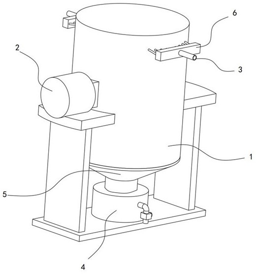
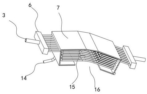
[0031] see Figure 1-9 , a vacuum low-temperature continuous drying equipment, including a straight cylinder 1 and a vacuum pump 2 connected thereto, a cone 5 is installed at the bottom of the straight cylinder 1, a liquid collection box 4 is installed at the bottom of the cone 5, and the inner top of the straight cylinder 1 is installed There are condensing components. The vacuum pump 2 is used to evacuate the inside of the straight cylinder 1 and the cone cylinder 5 to heat the material to promote the vaporization and precipitation of the moisture in the material, and the rising moisture is condensed by the condensing component to realize the drying effect on the material.

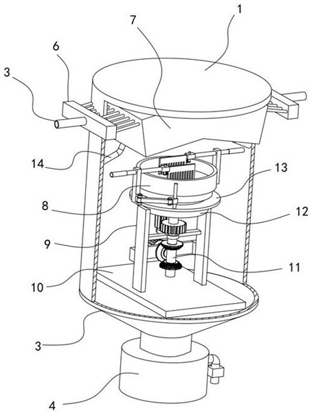
[0032] A horizontal frame 10 is fixed inside the straight cylinder 1, a vertical frame 9 is installed on the horizontal frame 10, a fixed ring plate 12 is fixed on the vertical frame 9, a fixed coaming 8 is fixed inside the straight cylinder 1, and the fixed coaming 8 slides A heating plate 28 is instal...

Embodiment 2

[0041] see Figure 1-9 , on the basis of Embodiment 1, in addition, the traction mechanism includes an outer ring plate 13 fixedly sleeved on the inner ring gear 27, a vertical rod 22 is fixed on the outer ring plate 13, and a lifting rod 22 is slidably installed on the vertical rod 22. Sleeve block 41, guide sleeve 19 is fixed on the inner wall of straight cylinder body 1, slide column 18 connected with evacuation mechanism is slidably installed on guide sleeve 19, fixed plate 20 is fixed on slide column 18, fixed plate 20 and lifting sleeve block 41 A connecting rod 21 is hinged therebetween.

[0042] The incomplete bevel gear 24 is installed in rotation on the vertical frame 9, and the driven bevel gear I25 and the driven bevel gear II26 are connected coaxially on the rotating shaft 11, and the incomplete bevel gear 24 is alternately connected with the driven bevel gear I25 and the driven bevel gear. II26 snap connection.

[0043] Based on the above-mentioned settings, th...


PUM


Abstract

The invention discloses vacuum low-temperature continuous drying equipment, and relates to the technical field of drying equipment, the vacuum low-temperature continuous drying equipment comprises a straight barrel and a vacuum pump connected with the straight barrel, a conical barrel is mounted at the bottom of the straight barrel, a horizontal frame is fixed in the straight barrel, a vertical frame is mounted on the horizontal frame, and a plurality of upper convex blocks are uniformly mounted at the bottom of a heating disc in the circumferential direction; a rotating disc is provided with a plurality of lower convex blocks which abut against the upper convex blocks in a sliding mode, the rotating shaft is connected with a rotating mechanism, the rotating mechanism is used for driving the heating disc to rotate, the rotating mechanism is provided with an outer ring plate, the outer ring plate is connected with an evacuation mechanism through a traction mechanism, and the traction mechanism is used for driving the evacuation mechanism to linearly slide relative to the heating disc; the transmission mechanism can drive the rotating disc to rotate, the lower convex blocks and the upper convex blocks on the rotating disc slidably abut against each other so that the heating disc can achieve the vibration effect, materials on the heating disc can be promoted to vibrate, the materials can be turned over and evenly heated, and precipitation of water is effectively promoted.

Description

technical field [0001] The invention relates to the technical field of drying equipment, in particular to a vacuum low-temperature continuous drying equipment. Background technique [0002] Vacuum drying, also known as analytic drying, is a drying method that puts materials under negative pressure conditions, and appropriately heats them to reach the boiling point under negative pressure, or cools down to make the materials solidify and then dry the materials through the melting point. [0003] Although the patent application publication number CN 110843354 A discloses a vacuum drying device, the vacuum drying device includes a chamber, an air inlet and at least one condensation recovery chamber, the chamber is used to place the substrate, and the air inlet A port is provided on one side of the chamber for introducing gas into the chamber to take away the solvent volatilized from the substrate, and the at least one condensation recovery chamber communicates with the chamber ...

Claims


Application Information

Patent Timeline
Patent Type & Authority Applications(China)
IPC IPC(8): F26B11/20F26B5/04F26B23/00F26B25/00F26B25/02F26B25/04F26B25/18
CPCF26B11/20F26B5/04F26B23/00F26B25/00F26B25/02F26B25/04F26B25/18
Inventor 田晓军
Owner ZHUCHENG XINZHENGDA MACHINERY CO LTD
Why Eureka
Try Eureka