
A telescopic rotary hydraulic cylinder for realizing rotary motion
A telescopic rotation and hydraulic cylinder technology, applied in the field of hydraulic cylinders, can solve the problems of lack of control structure that blocks the rotation power, inconvenient rotation control, etc., and achieve the effect of high applicability and convenient assembly
Patent Information
- Authority / Receiving Office
- CN · China
- Patent Type
- Patents(China)
- Current Assignee / Owner
- Publication Date
- 2022-04-08
Smart Images
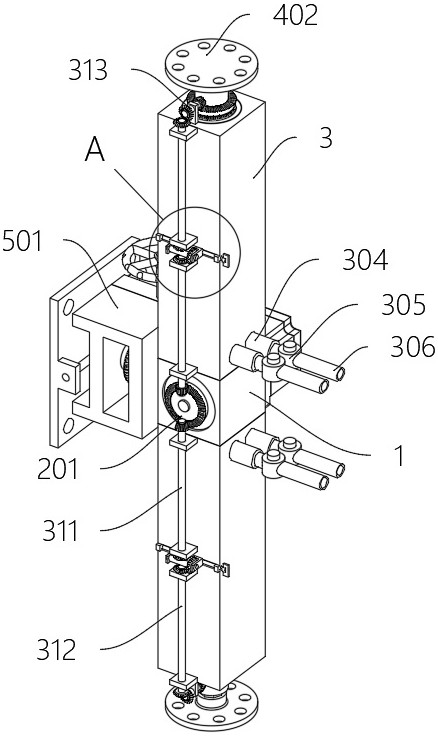
Figure 1 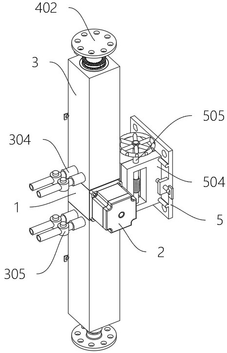
Figure 2 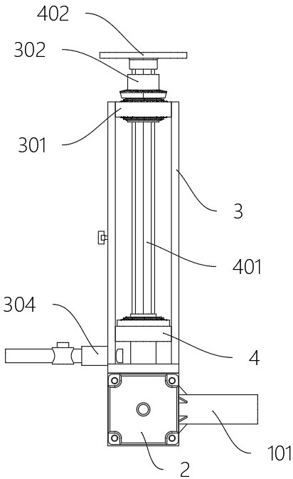
Figure 3
Abstract
Description
technical field
[0001] The invention relates to the technical field of hydraulic cylinders, in particular to a telescopic rotary hydraulic cylinder for realizing rotary motion. Background technique
[0002] A hydraulic cylinder is a component that provides mechanical power through hydraulic pressure. It can produce a telescopic effect and provide force to move or deform the equipment. It is a widely used mechanical component.
[0003] However, the currently used hydraulic cylinders adjust the angle of the connectors during the expansion and contraction process mainly by individually controlling the rotation of the connectors. It is inconvenient to directly provide the effect of rotation control during the expansion and contraction process, and lacks a control structure that blocks the rotation power. Contents of the invention
[0004] In view of this, the present invention provides a telescopic rotary hydraulic cylinder for realizing rotary motion, which has a rotating sle...
Examples
Embodiment
[0031] Example: Please refer to Figure 1 to Figure 8 :
[0032] The present invention proposes a telescopic rotary hydraulic cylinder for realizing rotation, comprising: a central component 1, a through hole is opened in the middle of the central component 1; a servo motor 2, and the servo motor 2 is fixedly arranged on the rear side of the central component 1 After the rotating shaft of the servo motor 2 passes through the front end of the central assembly 1, a bevel gear plate 201 is fixedly arranged; the hydraulic cylinder 3 is fixedly arranged at the upper and lower ends of the central assembly 1; the top middle of the hydraulic cylinder 3 is fixedly provided with a limit The middle of the ring 301 and the limit ring 301 cooperate with the double-row tapered roller bearing to rotate and set the rotating sleeve 302; the piston part 4, the piston part 4 is a T-shaped cylindrical structure, and the piston part 4 is slidingly arranged in the hydraulic cylinder 3; the central ...