Thermal composite lamination equipment and thermal composite lamination method

A technology of thermal compounding and lamination, applied in the direction of sustainable manufacturing/processing, electrochemical generators, electrical components, etc., can solve problems such as heat loss, low production efficiency, and insufficient compactness of composite laminations, and reduce heating power , high production efficiency, and compact thermal lamination equipment

Active Publication Date: 2021-10-26
SVOLT ENERGY TECHNOLOGY CO LTD
View PDF3 Cites 13 Cited by
  • Summary
  • Abstract
  • Description
  • Claims
  • Application Information

AI Technical Summary

Problems solved by technology

[0003] In the prior art, when the polar sheet and the diaphragm are heat-pressed together, the polar sheet is usually covered on the diaphragm first (or the diaphragm is covered on the pole In this way, in the heating and pressing process, in order to ensure that the separator and the polar s

Method used


Image

  • Thermal composite lamination equipment and thermal composite lamination method
  • Thermal composite lamination equipment and thermal composite lamination method
  • Thermal composite lamination equipment and thermal composite lamination method

Examples


Embodiment Construction

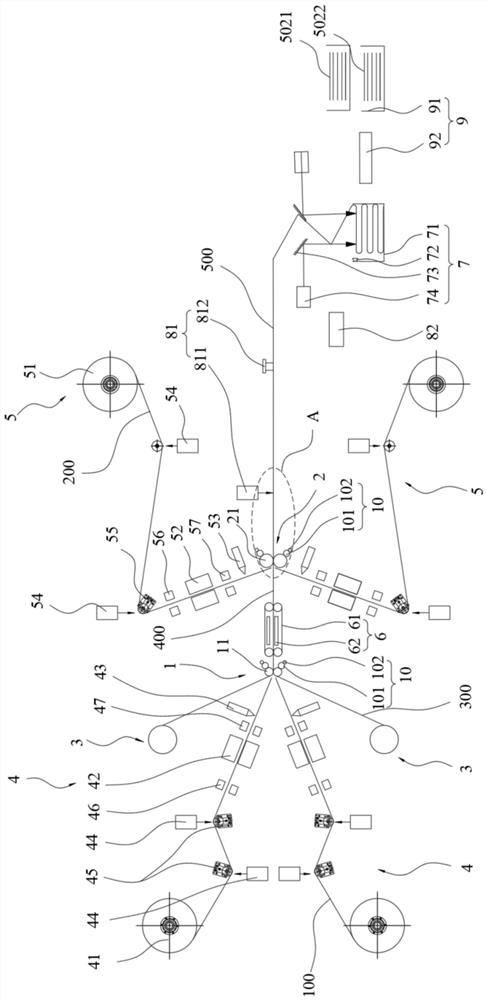
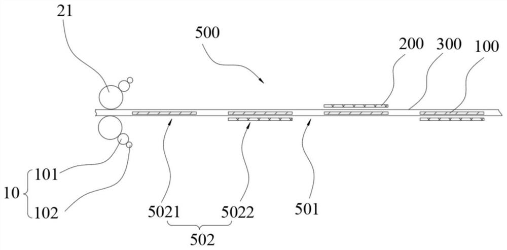
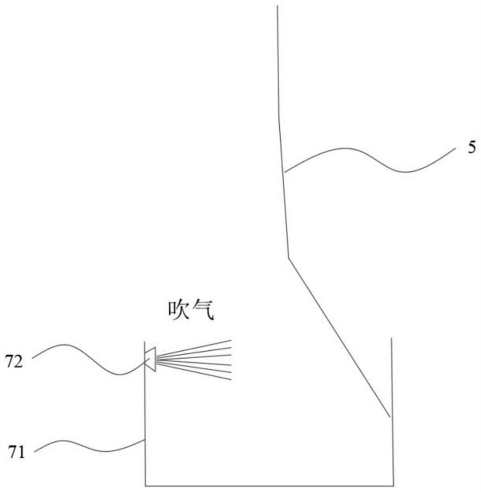
[0063] The present invention will be further described in detail below in conjunction with the accompanying drawings and embodiments. It should be understood that the specific embodiments described here are only used to explain the present invention, but not to limit the present invention. In addition, it should be noted that, for the convenience of description, only some structures related to the present invention are shown in the drawings but not all structures.

[0064] In the description of the present invention, unless otherwise clearly specified and limited, the terms "connected", "connected" and "fixed" should be understood in a broad sense, for example, it can be a fixed connection, a detachable connection, or an integrated ; It can be a mechanical connection or an electrical connection; it can be a direct connection or an indirect connection through an intermediary, and it can be the internal communication of two components or the interaction relationship between two ...


PUM


Abstract

The invention relates to the technical field of battery manufacturing, and discloses thermal composite lamination equipment and a thermal composite lamination method. The thermal composite lamination equipment comprises a first rolling mechanism, a second rolling mechanism, a main conveying mechanism, a first conveying mechanism, a heating conveying mechanism and a second conveying mechanism, and the main conveying mechanism can convey paired diaphragms to sequentially pass through the first rolling mechanism and the second rolling mechanism; the first conveying mechanism can feed a preheated first polar sheet with a preset size into the first rolling mechanism, the first polar sheet is clamped between the diaphragms, and the heating conveying mechanism can compound the diaphragms and the first polar sheet into an intermediate complex; and the second conveying mechanism can convey a preheated second polar piece with a preset size into the second rolling mechanism and enables the second polar piece to be located on the outer side of the diaphragm, and the second rolling mechanism presses the second polar piece and the middle composite body into a material belt. Energy loss is low, the structure is compact, and production efficiency is high.

Description

technical field [0001] The invention relates to the field of battery manufacturing equipment, in particular to a heat-composite lamination equipment and a heat-compound lamination method. Background technique [0002] Lithium-ion batteries have the advantages of high energy density, wide operating temperature range, excellent cycle performance, and no toxic and harmful substances, and are widely used as power batteries for automobiles. In the manufacturing process of lithium-ion batteries, it is necessary to separate the polar sheets of the opposite sex with a separator, and use hot pressing to combine the polar sheets and separators together, and then the combined material strips follow the Z-type lamination technology. stacked together. [0003] In the prior art, when the polar sheet and the diaphragm are thermally pressed together, the polar sheet is usually covered on the diaphragm (or the diaphragm is covered on the polar sheet), and then the overlapped polar sheet and...

Claims


Application Information

Patent Timeline
IPC IPC(8): H01M10/04H01M10/0583
CPCH01M10/0404H01M10/0583Y02P70/50Y02E60/10
Inventor 赵凯汪常王晓李昆芃
Owner SVOLT ENERGY TECHNOLOGY CO LTD
Why Eureka
Try Eureka