Eureka AIR delivers breakthrough ideas for toughest innovation challenges, trusted by R&D personnel around the world.

Multi-stage filtering oil separation tank

A grease trap and stage filtration technology, which is applied in the direction of filtration separation, filtration treatment, filtration circuit, etc., can solve the problems of basket blockage, low efficiency of oil pollution discharge, and unpleasant smell, so as to avoid blockage, improve treatment effect and work Efficiency, reduce the effect of accumulation clogging

Active Publication Date: 2021-10-29
深圳市合众源环保科技有限公司
View PDF2 Cites 0 Cited by
  • Summary
  • Abstract
  • Description
  • Claims
  • Application Information

AI Technical Summary

Problems solved by technology

[0003] However, in the actual operation of the traditional grease trap, since the kitchen sewage is not only a mixture of oil and water, but also inevitably contains some large-particle solid waste, such as vegetable leaves and bones, etc., it is necessary to use the corresponding basket However, in the long-term use process, these solid wastes will continue to accumulate, causing blockage of the basket, seriously affecting the sewage treatment effect and work efficiency; at the same time, in the actual oil discharge process, only rely on the effect of gravity , the oil floating on the upper layer is difficult to discharge completely, resulting in low oil discharge efficiency, and a large amount of oil will inevitably adhere to the inner wall of the oil separation area. If it is not cleaned, after a long period of use , not only will aggravate the corrosion damage to the equipment, but will also produce a very unpleasant smell; in addition, for different types of swill, the density of the internal oil will also vary, so there will be some differences in the situation of oil floating. The traditional fixed oil separator is not convenient to apply to various situations

Method used


Image

  • Multi-stage filtering oil separation tank
  • Multi-stage filtering oil separation tank
  • Multi-stage filtering oil separation tank

Examples


Embodiment Construction

[0031] In order to make the technical means, creative features, goals and effects achieved by the present invention easy to understand, the present invention will be further described below in conjunction with specific embodiments.

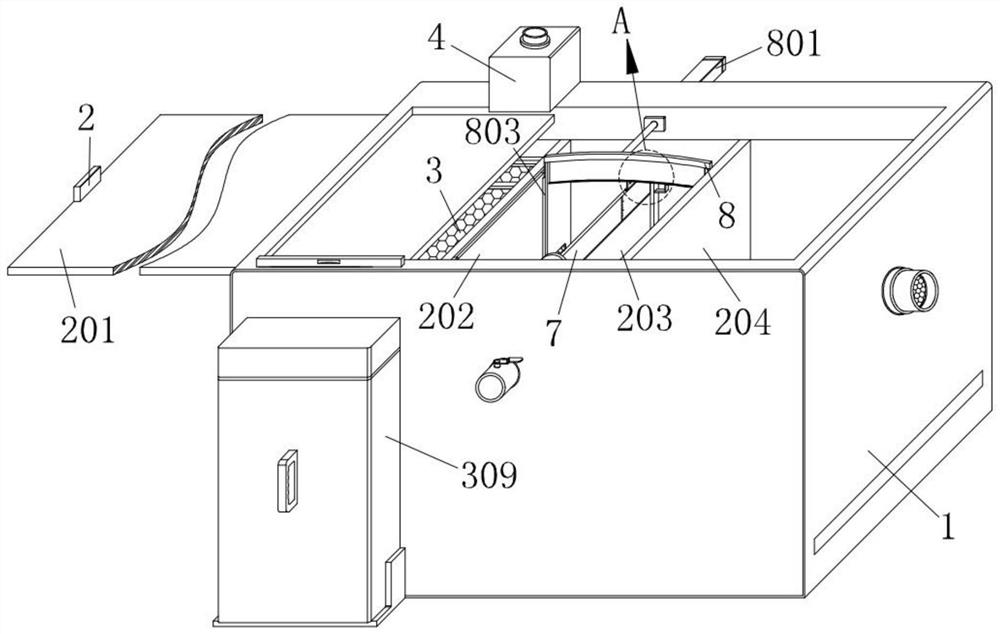
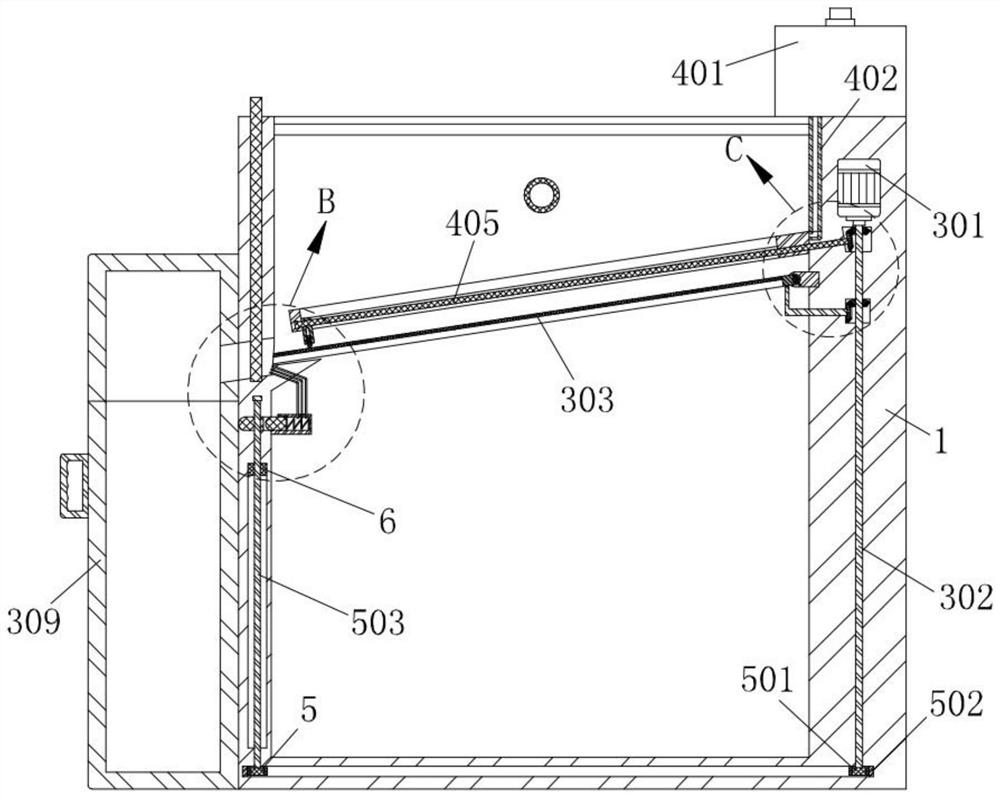
[0032] Such as Figure 1-Figure 11 As shown, a kind of multi-stage filter grease trap according to the present invention includes a tank body 1, a separation mechanism 2 is provided in the tank body 1, a screening mechanism 3 is provided in the tank body 1, and the screening mechanism 3 is arranged in the tank body 1. The mechanism 3 is provided with a sweeping mechanism 4, the pool body 1 is provided with a flushing mechanism 5, the separation mechanism 2 is provided with a cleaning mechanism 6, the separation mechanism 2 is provided with an adjustment mechanism 7, and the pool body 1 is provided with an oil scraping mechanism 8;

[0033] The screening mechanism 3 includes a fixed block 304, the pool body 1 is fixedly connected with a fixed bloc...


PUM


Abstract

The invention relates to the technical field of oil separation tanks, in particular to a multi-stage filtering oil separation tank which comprises a tank body, a separation mechanism arranged in the tank body, a screening mechanism arranged in the tank body, a scraping and sweeping mechanism arranged on the screening mechanism, a washing mechanism is arranged in the tank body, a sweeping mechanism is arranged on the separation mechanism, an adjusting mechanism is arranged on the separation mechanism, and an oil scraping mechanism is arranged on the tank body. Through cooperation of the screening mechanism and the scraping and sweeping mechanism, solid waste in sewage can be better treated, the phenomenon that a basket net is blocked by the solid waste is avoided, and the sewage treatment effect is improved; the adjusting mechanism is arranged in the separation mechanism, so that the height of an oil separation plate 203 can be conveniently adjusted, and the height is conveniently suitable for treatment conditions of different types of swill; the oil scraping mechanism is arranged in the tank body, so that the oil dirt floating on the surface can be pushed and scraped conveniently, the oil dirt can be discharged more smoothly, meanwhile, the oil dirt attached to the inner wall of equipment can be scraped conveniently, and peculiar smell is reduced.

Description

technical field [0001] The invention relates to the technical field of grease traps, in particular to a multistage filter grease trap. Background technique [0002] The grease trap is a wastewater pretreatment structure that uses the density difference between oil droplets and water to generate floating action to remove buoyant oily substances in oily wastewater. The structure of the grease trap mostly adopts the advection type. The oily waste water enters the rectangular grease trap through the water distribution tank and flows slowly along the horizontal direction. During the flow, the oil floats on the water surface and flows into the dehydration tank from the oil collecting pipe. In some catering establishments, grease traps are often used. [0003] However, in the actual operation of the traditional grease trap, since the kitchen sewage is not only a mixture of oil and water, but also inevitably contains some large-particle solid waste, such as vegetable leaves and bon...

Claims


Application Information

Patent Timeline
IPC IPC(8): B01D36/00C02F9/02C02F101/30
CPCB01D36/008C02F1/40C02F1/001C02F2101/30Y02A20/204
Inventor 黄仕叶周险峰
Owner 深圳市合众源环保科技有限公司
Why Eureka
Eureka Blog
Learn More