
Punch forming equipment for stainless steel kitchen ware and punch forming method

A stamping forming and stainless steel technology, applied in the stamping and forming field, can solve the problems of increasing labor intensity of workers, reducing positioning accuracy, shaking and tilting of stainless steel kitchen utensils, etc., so as to enhance the effect of steering and conveying, improve the accuracy of positioning, and improve the molding effect. Effect

Inactive Publication Date: 2021-10-29
何希甲
View PDF0 Cites 0 Cited by
  • Summary
  • Abstract
  • Description
  • Claims
  • Application Information

AI Technical Summary

Problems solved by technology

[0004] 1. The production of stainless steel kitchenware is often carried out in batches. Traditional stainless steel kitchenware stamping production operations require a lot of manpower to place and remove stainless steel kitchenware plates, which increases the labor intensity of workers. The sharp edges of the stainless steel kitchenware will also cause harm to the human body and reduce the working efficiency of the stamping and forming operation of stainless steel kitchenware.
[0005] 2. During the stamping and forming process of stainless steel kitchenware, it is difficult to support the circumferential positioning of the stainless steel kitchenware, which may easily cause the stainless steel kitchenware to shake and tilt during the stamping process, which reduces the accuracy of positioning during the stamping operation, and is difficult to During the stamping process, the bottom of the stainless steel kitchenware is supported by adsorption, which increases the probability of elastic deformation of the stainless steel kitchenware after stamping, and reduces the forming effect of the stainless steel kitchenware.

Method used


Image

  • Punch forming equipment for stainless steel kitchen ware and punch forming method
  • Punch forming equipment for stainless steel kitchen ware and punch forming method
  • Punch forming equipment for stainless steel kitchen ware and punch forming method

Examples


Embodiment Construction

[0042] In order to make the technical means realized by the present invention, creative features, goals and effects easy to understand, the following combination Figure 1 to Figure 13 , to further elaborate the present invention.

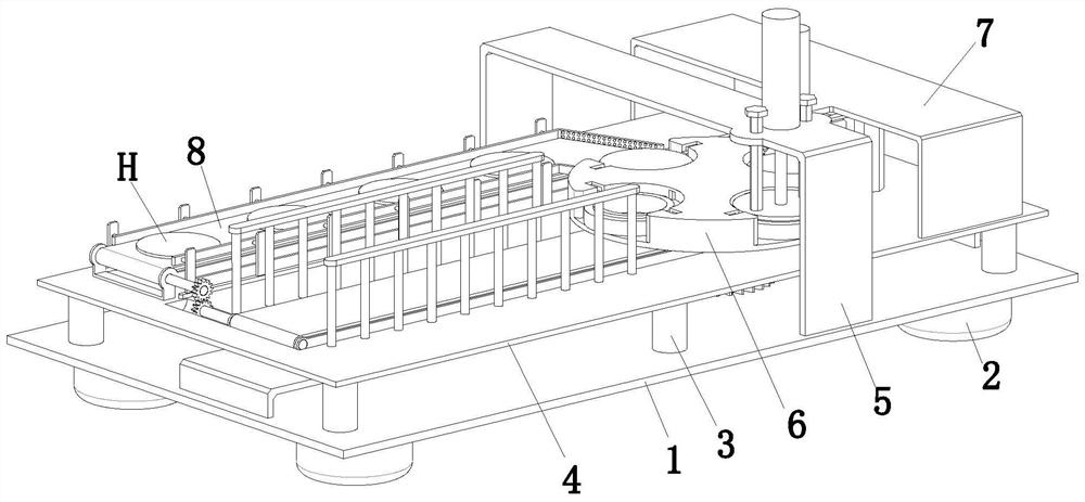
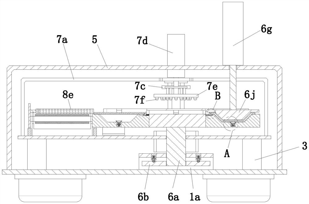
[0043] refer to figure 1 , a stamping and forming equipment for stainless steel kitchen utensils, including an installation base plate 1, support feet 2, support rods 3, a stamping base plate 4, a stamping frame 5, a stamping mechanism 6, a positioning mechanism 7 and a conveying mechanism 8, the installation base plate 1 Support feet 2 are evenly installed at the corners around the lower end surface, support rods 3 are evenly installed on both sides of the upper end surface of the stamping base plate 4, and the upper end of the support rods 3 is jointly installed with a stamping base plate 4, and a conveying mechanism 8 is installed on the stamping base plate 4. The upper end of the bottom plate 1 is equipped with a stamping frame 5 with an openi...


PUM


Abstract

The invention provides punch forming equipment for stainless steel kitchen ware and a punch forming method. The punch forming equipment comprises a mounting bottom plate, supporting legs, supporting rods, a punching bottom plate, a punching left square bracket-shaped frame, a punching mechanism, a positioning mechanism and a conveying mechanism. According to the punch forming equipment, the problems that in the stainless steel kitchen ware punch forming operation process, a large amount of manpower is usually needed to carry out placement and taking-out work on stainless steel kitchen ware plates, the labor intensity of workers is increased, traditional punching equipment is difficult to carry out circumferential positioning and support on the stainless steel kitchen ware, the stainless steel kitchen ware is easy to shake and incline in the punching process, the positioning accuracy during punching operation is reduced, the bottom of the stainless steel kitchen ware is difficult to adsorb and support in the punching process, the elastic deformation probability of the stainless steel kitchen ware after punching is increased, and the forming effect of the stainless steel kitchen ware is reduced are solved.

Description

technical field [0001] The invention relates to the technical field of stamping forming, in particular to a stamping forming equipment and a stamping forming method for stainless steel kitchen utensils. Background technique [0002] Stainless steel is the abbreviation of stainless acid-resistant steel, and the steel grades that are resistant to weak corrosive media such as air, steam, water, or have stainless properties are called stainless steel; The steel type is called acid-resistant steel. [0003] Due to the difference in chemical composition of the two, their corrosion resistance is different. Ordinary stainless steel is generally not resistant to chemical medium corrosion, while acid-resistant steel is generally stainless. The term "stainless steel" does not simply refer to one kind of stainless steel, but refers to more than one hundred kinds of industrial stainless steels, and each developed stainless steel has good performance in its specific application field. K...

Claims


Application Information

Patent Timeline
IPC IPC(8): B21D53/60B21D22/02B21D43/12B21D43/02B21D43/00B21D45/02
CPCB21D53/60B21D22/02B21D43/12B21D43/023B21D43/003B21D45/02
Inventor 何希甲
Owner 何希甲
Learn More