Roller carrier capable of automatically adapting to rolling shaft and automatically locking and application method of roller carrier
An automatic locking and automatic adaptation technology, applied in the field of roller frames, can solve problems such as low efficiency and inability to automatically adjust the position, and achieve the effects of reducing cumbersomeness, ingenious design, and simple structure
- Summary
- Abstract
- Description
- Claims
- Application Information
AI Technical Summary
Problems solved by technology
Method used
Image
Examples
Embodiment 1
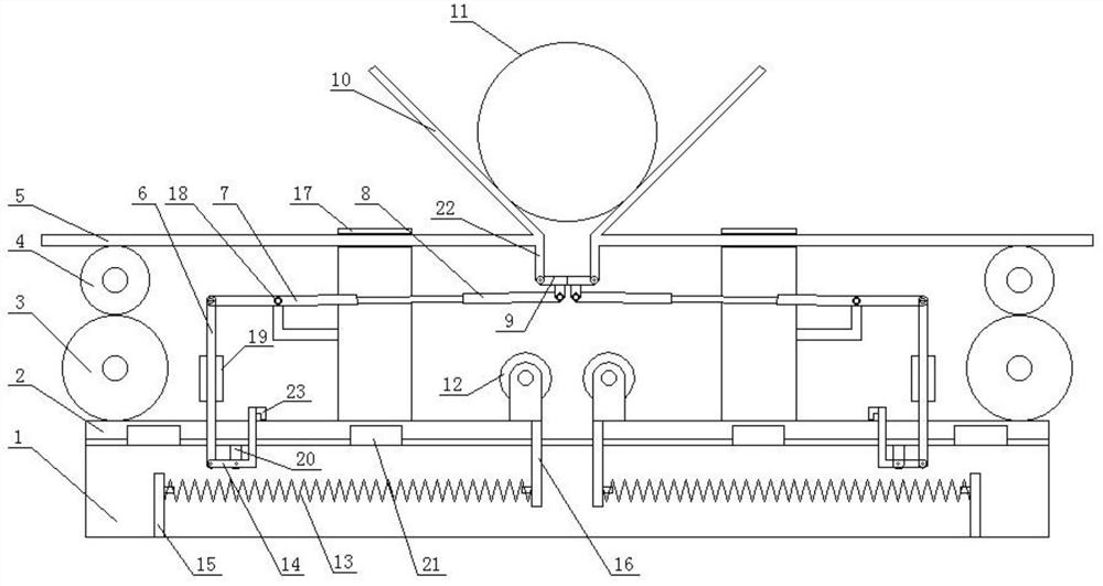
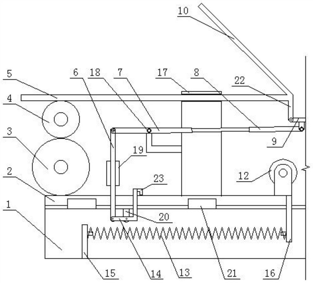
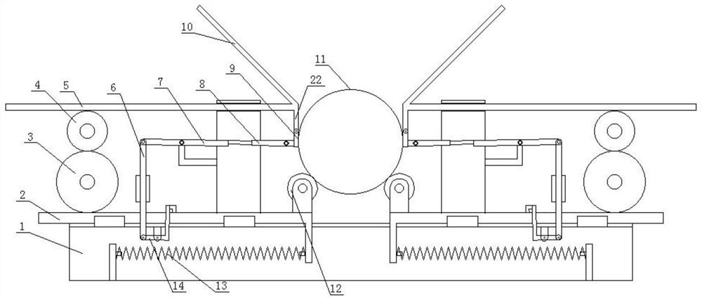
[0027] Such as Figure 1-3 As shown, this embodiment proposes a roller frame that automatically adapts to the rollers, including a frame 1, and two groups of symmetrically arranged traverse assemblies are arranged above the frame 1, and the traverse assemblies include an upper movement mechanism and an upper movement mechanism. Linked lower moving mechanism, wherein the lower moving mechanism includes a first rack 2 slidingly connected with the frame 1, the first rack 2 can slide left and right along the frame 1; one end of the first rack 2 is connected with a roller frame, and the roller The support roller 12 is arranged on the frame; a spring 13 for resetting is also connected under the first rack 2, and the other end of the spring 13 is connected with the frame 1; the upper moving mechanism includes a second rack 5, and the frame 1 is connected with a support Seat 17, the second rack 5 is slidingly connected with the support seat 17 and moves left and right along the suppor...
Embodiment 2
[0036] Continue to refer to the attached Figure 1-3 , on the basis of Embodiment 1, this embodiment proposes a roller frame that automatically adapts to the rollers and can be automatically locked. Each set of traversing components is connected with a set of locking mechanisms, and the two sets of locking mechanisms are also symmetrical. Setting; locking mechanism comprises movable block 9, and movable block 9 is T-shaped; The bottom of baffle plate 10 is connected with vertically arranged guide bar 22, and one end of movable block 9 is hinged with the bottom end of guide bar 22, and movable block 9 is connected with the bottom of guide bar 22. A torsion spring (not shown) is arranged between the guide rods 22, which can be set conventionally. The torsion spring provides power for the reset after the rotation of the movable block 9; A lever 7 is connected, and the telescopic rod 8 is used for lateral movement distance compensation; the lever 7 is hinged on the bracket through...
PUM
 Abstract
Description
Claims
Application Information
 - R&D
- Intellectual Property
- Life Sciences
- Materials
- Tech Scout
- Unparalleled Data Quality
- Higher Quality Content
- 60% Fewer Hallucinations
Browse by: Latest US Patents, China's latest patents, Technical Efficacy Thesaurus, Application Domain, Technology Topic, Popular Technical Reports.
© 2025 PatSnap. All rights reserved.Legal|Privacy policy|Modern Slavery Act Transparency Statement|Sitemap|About US| Contact US: help@patsnap.com


