
Spindle cooling structure with annular cooling and axial cooling connected in series and machine tool

A cooling structure and spindle technology, applied in metal processing machinery parts, maintenance and safety accessories, metal processing equipment, etc., can solve the problems of large distance between installation surfaces, and it is difficult to reduce the temperature rise of the front end of the spindle, so as to reduce the temperature rise of the spindle, Compact structure, the effect of reducing the temperature rise of the spindle

Inactive Publication Date: 2021-10-29
SHANDONG AGRI & ENG UNIV
View PDF0 Cites 2 Cited by
  • Summary
  • Abstract
  • Description
  • Claims
  • Application Information

AI Technical Summary

Problems solved by technology

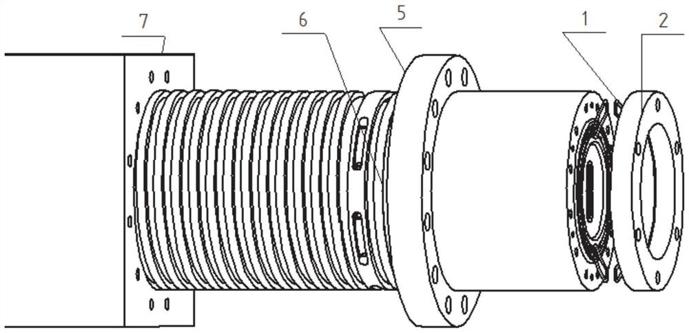
[0004] The purpose of the present invention is to provide a cooling structure for the spindle of the CNC machining center, aiming to solve the problem that the distance between the nose of the spindle and the mounting surface of the spindle sleeve is relatively large, the bearing at the front of the spindle is far away from the cooling range of the cooling groove, and it is difficult to reduce the temperature rise at the front of the spindle

Method used


Image

  • Spindle cooling structure with annular cooling and axial cooling connected in series and machine tool
  • Spindle cooling structure with annular cooling and axial cooling connected in series and machine tool
  • Spindle cooling structure with annular cooling and axial cooling connected in series and machine tool

Examples


Embodiment Construction

[0033] It should be noted that the following detailed description is exemplary and intended to provide further explanation of the present invention. Unless defined otherwise, all technical and scientific terms used herein have the same meaning as commonly understood by one of ordinary skill in the art to which this invention belongs.

[0034] It should be noted that the terminology used here is only for describing specific embodiments, and is not intended to limit exemplary embodiments according to the present invention. As used herein, unless the invention clearly states otherwise, the singular form is also intended to include the plural form. In addition, it should also be understood that when the terms "comprising" and / or "comprising" are used in this specification, their Indicate the presence of features, steps, operations, means, components and / or combinations thereof;

[0035] For the convenience of description, if the words "left" and "right" appear in the present inve...


PUM


Abstract

The invention discloses a spindle cooling structure with annular cooling and axial cooling connected in series and a machine tool. The spindle cooling structure mainly comprises a spindle sleeve. A cooling loop on the spindle sleeve is formed by connecting two parts in series, namely a spiral groove cooling pipeline and axial hole cooling pipelines sequentially connected in series, and the two parts of pipelines are connected in series to form the circulating cooling loop. The cooling pipeline at the position of a spiral cooling groove and the cooling pipelines formed by connecting the multiple axial holes in series are connected in series to form the complete cooling loop, and cooling liquid entering the cooling loop flows in a circulating manner.

Description

technical field [0001] The invention relates to the technical field of machine tool spindle cooling, in particular to a spindle cooling structure and a machine tool in which the nose end of the machine tool spindle is as close as possible to a workpiece. Background technique [0002] With the rapid development of the manufacturing industry, the market has higher requirements for the performance of CNC machining centers, not only requiring high spindle speed, but also requiring small spindle temperature rise to maintain the machining accuracy of CNC machining centers. The CNC machining center drives the tool to rotate at high speed through the spindle to realize the machining of the workpiece. When the spindle rotates at high speed, on the one hand, the spindle drives the cutting tool to generate a lot of heat, and on the other hand, the high-speed rotation of the bearing also generates a lot of heat, which eventually causes the temperature of the spindle to rise; which in tu...

Claims


Application Information

Patent Timeline
Patent Type & Authority Applications(China)
IPC IPC(8): B23Q11/12
CPCB23Q11/127
Inventor 林小亮宋卫海李曰阳成小飞刘鑫
Owner SHANDONG AGRI & ENG UNIV
Learn More