
Unmanned aerial vehicle take-off power assisting device arranged on water surface

A technology of booster device and unmanned aerial vehicle, applied in the field of unmanned aerial vehicle, can solve the problems of slow take-off speed of unmanned aerial vehicle, weak endurance, unmanned damage and so on.

Inactive Publication Date: 2021-10-29
湖州泰益智能科技有限公司
View PDF0 Cites 0 Cited by
  • Summary
  • Abstract
  • Description
  • Claims
  • Application Information

AI Technical Summary

Problems solved by technology

[0003] However, at present, unmanned drones have the disadvantage of weak battery life. Therefore, although drones have strong detection capabilities on the ground, they are weak in water applications, mainly because drones cannot Looking for a place to land on the ground, so it is necessary to maintain a certain amount of energy for the return of the drone, so there are currently some planes for the landing of the drone, but these platforms are usually mainly floating on the water for the landing of the drone , when the UAV needs to take off, these platforms will not be able to play a very good boosting effect, which will make the UAV’s take-off speed relatively slow, making the UAV’s flight unstable during the take-off stage, and even appear to have no Human-machine contact with the water surface causes no one to be damaged, etc.

Method used


Image

  • Unmanned aerial vehicle take-off power assisting device arranged on water surface
  • Unmanned aerial vehicle take-off power assisting device arranged on water surface
  • Unmanned aerial vehicle take-off power assisting device arranged on water surface

Examples


Embodiment Construction

[0024] The following examples are for illustrative purposes only and are not intended to limit the scope of the invention.

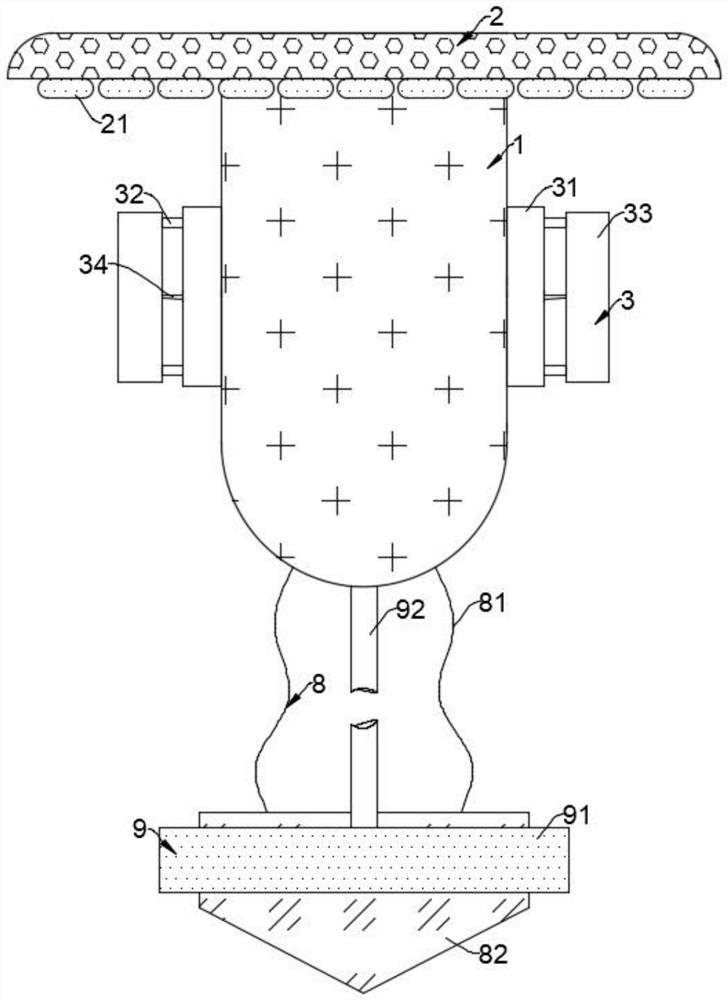
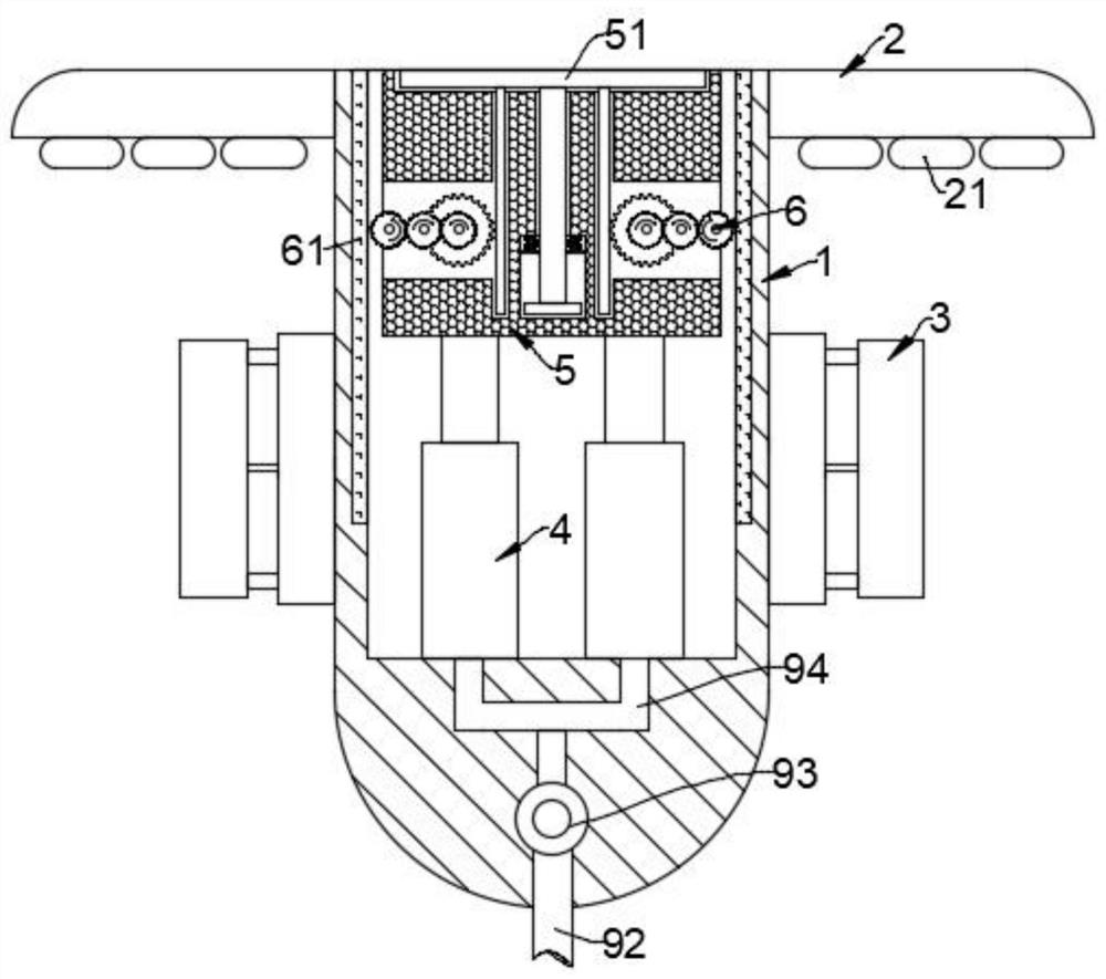
[0025] like Figure 1-6 As shown, a UAV take-off assisting device placed on the water surface includes a cylinder body 1, an annular floating plate 2 is fixedly connected to the top of the side wall of the cylinder body 1, and a plurality of buoyancy bladders 21 are fixedly connected to the bottom end of the annular floating plate 2, By arranging the annular floating plate 2 and the buoyancy bag 21, the device can be floated on the water surface, and a lifting platform can be provided for the drone horizontally.

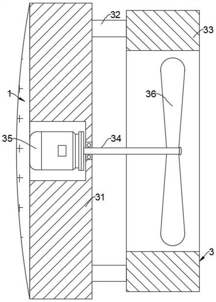
[0026] A plurality of driving mechanisms 3 are fixedly connected to the side wall of the cylinder body 1. The driving mechanism 3 is composed of a fixed block 31, a connecting rod 32, a fixed ring 33, a drive shaft 34, a motor 35 and a turbine 36. The fixed block 31 is fixedly connected to the cylinder body 1. On the outer wall, the motor 35 i...


PUM


Abstract

The invention belongs to the field of unmanned aerial vehicles, and particularly relates to an unmanned aerial vehicle take-off power assisting device arranged on the water surface. The unmanned aerial vehicle take-off power assisting device comprises a cylinder body, an annular floating plate is fixedly connected to the top end of the side wall of the cylinder body, a plurality of buoyancy bags are fixedly connected to the bottom end of the annular floating plate, a plurality of driving mechanisms are fixedly connected to the side wall of the cylinder body, a power assisting cavity is formed in the cylinder body, and a plurality of air pressure pieces are fixedly connected to the inner bottom wall of the power assisting cavity. In the stage that the unmanned aerial vehicle needs to take off, the air pressure pieces can be rapidly stretched by utilizing the tension effect of the bag body and the water pressure effect, then a supporting block can be rapidly bounced upwards, first-stage acceleration of the supporting block and a supporting plate is achieved, meanwhile, the supporting plate can move upwards more quickly relative to the supporting block through a transmission mechanism, so that second-stage acceleration of the supporting plate is achieved, and it is ensured that the unmanned aerial vehicle located on the supporting plate can have good ejection and flying assisting effects through the second-stage acceleration.

Description

technical field [0001] The invention belongs to the field of unmanned aerial vehicles, and in particular relates to a take-off assisting device for an unmanned aerial vehicle placed on the water surface. Background technique [0002] Unmanned aircraft, referred to as "UAV", is an unmanned aircraft controlled by radio remote control equipment and self-contained program control device, or is completely or intermittently operated autonomously by the on-board computer. A highly automated and intelligent flight equipment is widely used in various fields because of its unique advantages such as small size, light weight, wide range of uses, simple air crew support, and not limited by human physiological conditions. [0003] However, at present, unmanned drones have the disadvantage of weak endurance. Therefore, although drones have strong detection capabilities on the ground, they are weak in water applications, mainly because drones cannot Looking for a place to land on the groun...

Claims


Application Information

Patent Timeline
Patent Type & Authority Applications(China)
IPC IPC(8): B64F1/06B63B35/50
CPCB64F1/06B63B35/50
Inventor 沈明明
Owner 湖州泰益智能科技有限公司
Learn More