Bottle body edge rolling equipment suitable for vehicle-mounted liquefied gas bottle

A technology for liquefied gas cylinders and bottle bodies, which is applied in mechanical equipment, applications, household appliances, etc. It can solve the problems of hidden safety hazards in adjusting equipment, inability to form a complete circle, and increase labor intensity of workers, so as to improve the quality of rolling circles and The effect of reducing rolling cost and improving rolling efficiency

Inactive Publication Date: 2021-10-29
WUHU HAIGE RUIDE SCI & TECH
View PDF1 Cites 0 Cited by
  • Summary
  • Abstract
  • Description
  • Claims
  • Application Information

AI Technical Summary

Problems solved by technology

[0005] 1. During the transportation of the steel plate, its surface is easily contaminated with dust, and some steel scraps adhered to the surface. When the roll is rolled, these impurities are likely to cause pits on the surface of the steel plate, thereby reducing the roundness of the bottle body. quality
[0006] 2. When grabbing the steel plate, there is no limit, and the steel plate is prone to skew during transportation, which makes the steel plate deformed during coiling, that is, it cannot be formed into a complete circle, which reduces the rolling effect
[0007] 3. It needs to be loaded by workers, and at the same time, manual assistance is required during the processing process, which not only increases the labor intensity of workers, but also reduces the processing efficiency, and there are certain safety hazards when workers adjust the equipment

Method used


Image

  • Bottle body edge rolling equipment suitable for vehicle-mounted liquefied gas bottle
  • Bottle body edge rolling equipment suitable for vehicle-mounted liquefied gas bottle
  • Bottle body edge rolling equipment suitable for vehicle-mounted liquefied gas bottle

Examples


Embodiment Construction

[0037] The technical solutions of the present invention will be further described below in conjunction with the accompanying drawings and through specific implementation methods.

[0038] Wherein, the accompanying drawings are only for illustrative purposes, showing only schematic diagrams, rather than physical drawings, and should not be construed as limitations on this patent; in order to better illustrate the embodiments of the present invention, some parts of the accompanying drawings will be omitted, Enlarged or reduced, does not represent actual product size.

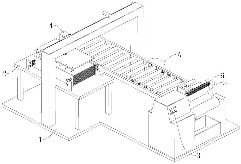
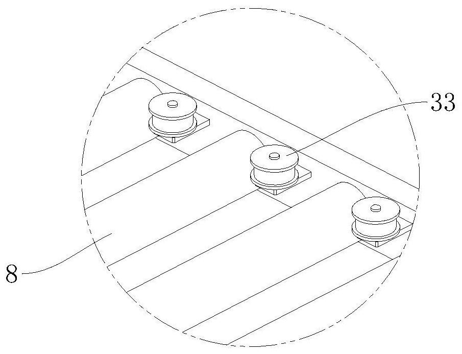
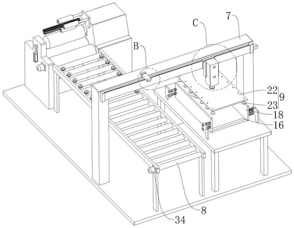
[0039] refer to Figure 1 to Figure 9Shown is a bottle body rolling device suitable for vehicle-mounted liquefied gas cylinders, including a base 1 and a placement table 2, and is characterized in that it also includes a controller 3, a conveying mechanism 4, a winding mechanism 5 and a cleaning mechanism 6, and the conveying The mechanism 4 is arranged on the top of the base 1 to convey the steel plate used for ...


PUM

PropertyMeasurementUnit
pressureaaaaaaaaaa

Abstract

The invention relates to the technical field of gas cylinder machining, in particular to bottle body edge rolling equipment suitable for a vehicle-mounted liquefied gas bottle. The equipment comprises a base and a placing table, and is characterized by further comprising a controller, a conveying mechanism, a winding mechanism and a cleaning mechanism, wherein the conveying mechanism is arranged at the top of the base and used for conveying a steel plate for edge rolling; the conveying mechanism comprises a gantry, a conveyor, a grabbing component and a sliding component; the winding mechanism comprises a pressing roller, a driving component, three conveying rollers and three sleeve rollers; the cleaning mechanism comprises a cleaning brush and a transmission component; the cleaning brush is inserted into the outer wall of a rectangular plate through a hinge shaft; the transmission component is arranged between the cleaning brush and one conveying roller; and the conveyor, the grabbing component, the sliding component and the driving component are all electrically connected with the controller. According to the bottle body edge rolling equipment suitable for the vehicle-mounted liquefied gas bottle, manual feeding is not needed, the automation degree is higher, the machining efficiency is higher, meanwhile, the edge rolling degree is better, and the edge rolling quality and effect of the bottle body can be guaranteed.

Description

technical field [0001] The invention relates to the technical field of gas cylinder processing, in particular to a bottle body rolling device suitable for vehicle-mounted liquefied gas cylinders. Background technique [0002] The liquefied gas tank refers to the storage tank used to store liquefied gas. When there is liquefied gas inside, the pressure is very high, and a slight misoperation may cause an explosion. It is a special equipment. The product itself is made of steel and has a certain compressive capacity. The maximum withstand pressure of the liquefied gas cylinder is 2.1 MPa. There are many kinds of existing liquefied gas cylinders, some of which are used in vehicles. The body of a traditional liquefied gas cylinder includes a bottle body, a top cover and a bottom cover. Usually, during processing, the flat steel plate is first rolled into a cylindrical shape, and then the The top cover and bottom cover are welded to the two ends of the cylindrical bottle body, ...

Claims


Application Information

Patent Timeline
Patent Type & Authority Applications(China)
IPC IPC(8): F17C1/14B21D5/14B21D51/24
CPCF17C1/14B21D5/14B21D51/24F17C2221/033
Inventor 郭荣军
Owner WUHU HAIGE RUIDE SCI & TECH
Why Eureka
Try Eureka