AI technical title is built by Patsnap AI team. It summarizes the technical point description of the patent document.
A storage structure and hydrogen tank technology, applied in the direction of gas processing/storage, gas/liquid distribution and storage, container discharge methods, etc., can solve the problems of not being able to be fixed in the same device, so as to improve safety and stability Effect
Active Publication Date: 2021-10-29
SICHUAN HUANENG HYDROGEN TECH CO LTD +9
View PDF16 Cites 1 Cited by
Summary
Abstract
Description
Claims
Application Information
AI Technical Summary
This helps you quickly interpret patents by identifying the three key elements:
Problems solved by technology
Method used
Benefits of technology
Problems solved by technology
[0003] However, the devices currently on the market for transporting hydrogen cylinders use a unified fixing method when they are actually used. When hydrogen cylinders of different sizes need to be transported, they often cannot be fixed well with the same device.
Method used
Image
Click on the blue label to locate the original text in one second.
Reading with bidirectional positioning of images and text.
Examples
Embodiment 1
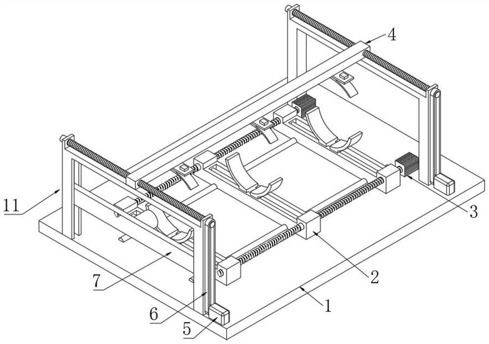
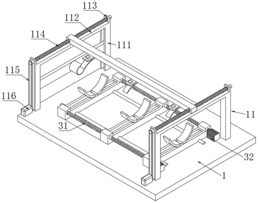
[0050] Such as figure 1 , figure 2 As shown, the present invention provides a highly reliable hydrogen tank storage structure, comprising:
[0051] Base plate 1; both sides of base plate 1 are provided with mounting frame 11 perpendicular to the base plate, mounting frame 11 includes crossbeam 112 and two columns 111, crossbeam 11 is installed on the top of two columns 111, the bottom of two columns 111 is all connected with base plate 1 connection;
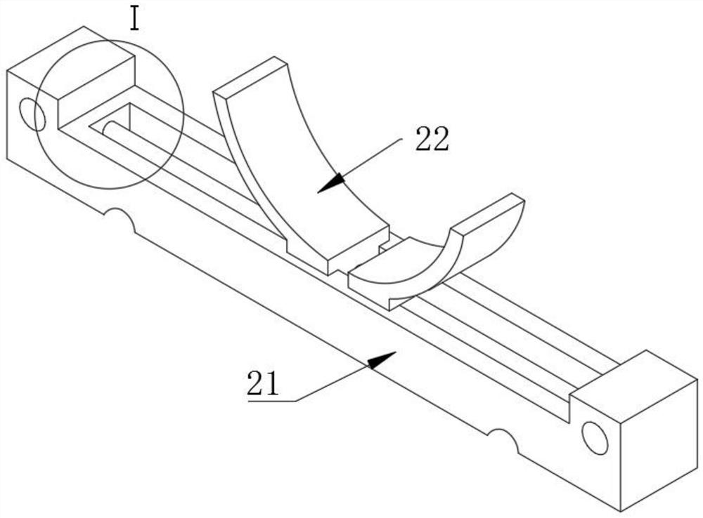
[0052] Three clamping devices 2; the three clamping devices 2 are arranged along the same horizontal direction, and each clamping device 2 is slidably mounted on the bottom plate 1, and the sliding direction is the first direction, the first direction is perpendicular to the vertical direction, and the clamping device 2 is slidably mounted on the bottom plate 1. The holding device 2 is parallel to the mounting frame 11, and the hydrogen tank is placed on the three holding devices;
[0053] Drive mechanism; used to drive the t...
Embodiment 2
[0078] Such as Figure 12 As shown, this embodiment is further improved on the basis of Embodiment 1: an extruding device 8 is arranged on the right side of the bottom plate, and the extruding device 8 cooperates with the valve protection device 7 to further fix the hydrogen tank 100 front and back, improving Stability of the hydrogen tank 100.
[0079] Extrusion device 8 comprises fixed plate 81, electric push rod 82, extruding plate 83, and fixed plate 81 is installed on the base plate 1 and is vertical with base plate 1, and electric push rod 82 is installed on the fixed plate 81, and the push rod of electric push rod The end is connected with the extruding plate 83, and the extruding plate 83 is used to compress the bottom of the hydrogen tank 100.
[0080] When the present invention is in use: first adjust the position of the clamping device 2 according to the length of the hydrogen tank, start the driving mechanism to adjust the position of the clamping device, ensure t...
PUM
Abstract
The invention provides a high-reliability hydrogen tank storage structure. The high-reliability hydrogen tank storage structure comprises a bottom plate, three clamping devices, driving mechanisms and downward pressing devices, mounting frames perpendicular to the bottom plate are arranged on the two sides of the bottom plate, each mounting frame comprises a cross beam and two stand columns, the cross beam is mounted at the tops of the two stand columns, and the bottoms of the two stand columns are connected with the bottom plate; the three clamping devices are arranged in the same horizontal direction, each clamping device is slidably mounted on the bottom plate, the sliding direction is the first direction, the first direction is perpendicular to the vertical direction, and the clamping devices are parallel to the mounting frames; the driving mechanisms are used for driving the two clamping devices at two ends to slide; and the two ends of the downward pressing devices are rotationally connected with the two mounting frames correspondingly, and the downward pressing devices are located above the clamping devices. The high-reliability hydrogen tank storage structure can store and fix hydrogen tanks with different sizes, and is good in fixing effect and high in safety.
Description
technical field [0001] The invention relates to the technical field of hydrogen tank storage and fixing, in particular to a highly reliable hydrogen tank storage structure. Background technique [0002] Hydrogen energy refers to the chemical energy released by the chemical reaction of hydrogen and oxygen. It is a clean secondary energy source with high energy density, high combustion calorific value, wide source, storable, renewable, electric and combustible, and zero pollution. And the advantages of zero carbon emissions, help to solve the energy crisis and environmental pollution and other issues, the transportation of hydrogen energy usually requires the use of hydrogen cylinders. [0003] However, the current devices for transporting hydrogen cylinders on the market all adopt a unified fixing method when they are actually used. When it is necessary to transport hydrogen cylinders of different sizes, they often cannot be well fixed by the same device. Contents of the in...
Claims
Application Information
Patent Timeline
Application Date:The date an application was filed.
Publication Date:The date a patent or application was officially published.
First Publication Date:The earliest publication date of a patent with the same application number.
Issue Date:Publication date of the patent grant document.
PCT Entry Date:The Entry date of PCT National Phase.
Estimated Expiry Date:The statutory expiry date of a patent right according to the Patent Law, and it is the longest term of protection that the patent right can achieve without the termination of the patent right due to other reasons(Term extension factor has been taken into account ).
Invalid Date:Actual expiry date is based on effective date or publication date of legal transaction data of invalid patent.

