
Point light source with controllable light lens

A point light source and lens technology, applied in the field of point light sources, can solve the problems of reducing production efficiency, low efficiency, and increasing production cost, and achieves the effects of improving assembly efficiency, simple and convenient installation, and improving assembly efficiency.

Active Publication Date: 2021-10-29
安徽睿翔光电科技有限公司
View PDF11 Cites 0 Cited by
  • Summary
  • Abstract
  • Description
  • Claims
  • Application Information

AI Technical Summary

Problems solved by technology

When assembling the LED point light source, the front cover and the lens need to be precisely matched, and then fixedly connected by welding or pasting equipment, which not only increases the production cost, but also greatly reduces the production efficiency; The front cover and the back cover of the LED point light source are assembled, which is inefficient
[0003] Common LED point light source lamps often have poor waterproof performance due to the insufficient structural connection of the lamp itself. Once water enters, it will inevitably affect the luminous efficiency of the LED point light source lamp and even cause damage to the electronic components.
The existing LED point light source lamps cannot adjust the luminous angle of the internal LED point light source lamps. It is often necessary to refit or overall adjust the LED point light source lamp fixing frame, which reduces the scope of application of the LED point light source lamps.

Method used


Image

  • Point light source with controllable light lens
  • Point light source with controllable light lens
  • Point light source with controllable light lens

Examples


Embodiment Construction

[0028] The following will clearly and completely describe the technical solutions in the embodiments of the present invention with reference to the accompanying drawings in the embodiments of the present invention. Obviously, the described embodiments are only some, not all, embodiments of the present invention. Based on the embodiments of the present invention, all other embodiments obtained by persons of ordinary skill in the art without making creative efforts belong to the protection scope of the present invention.

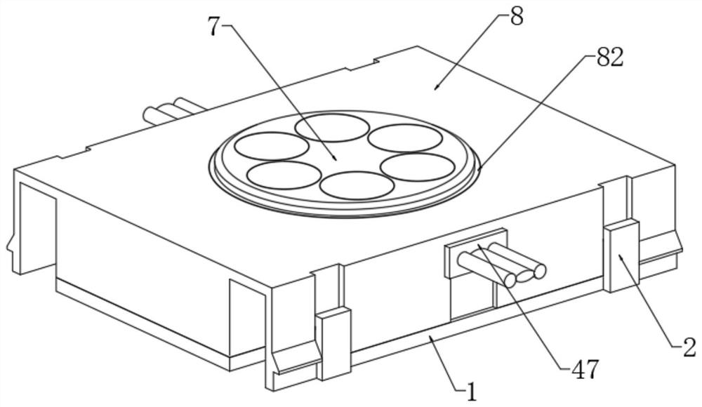
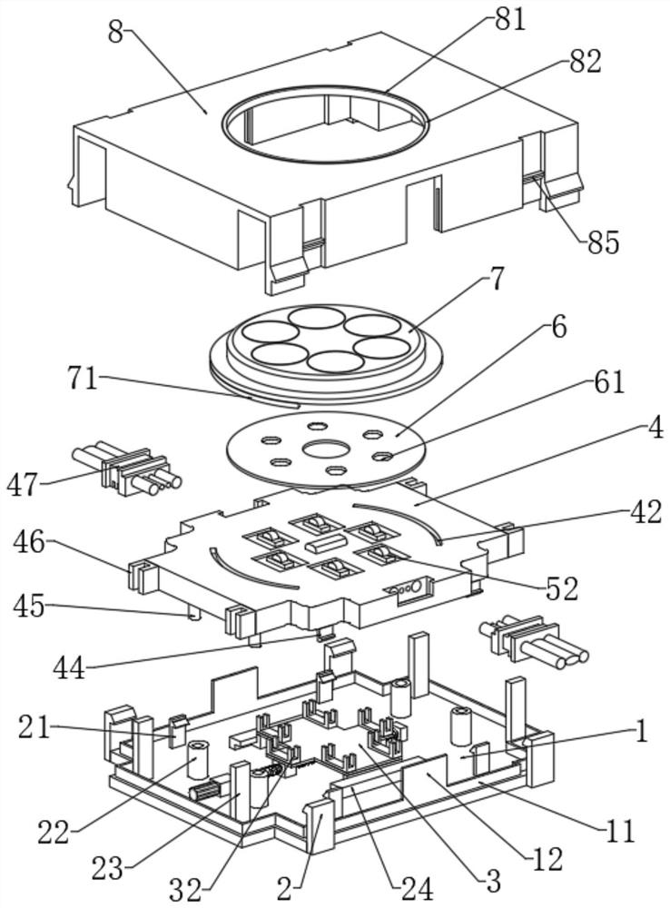
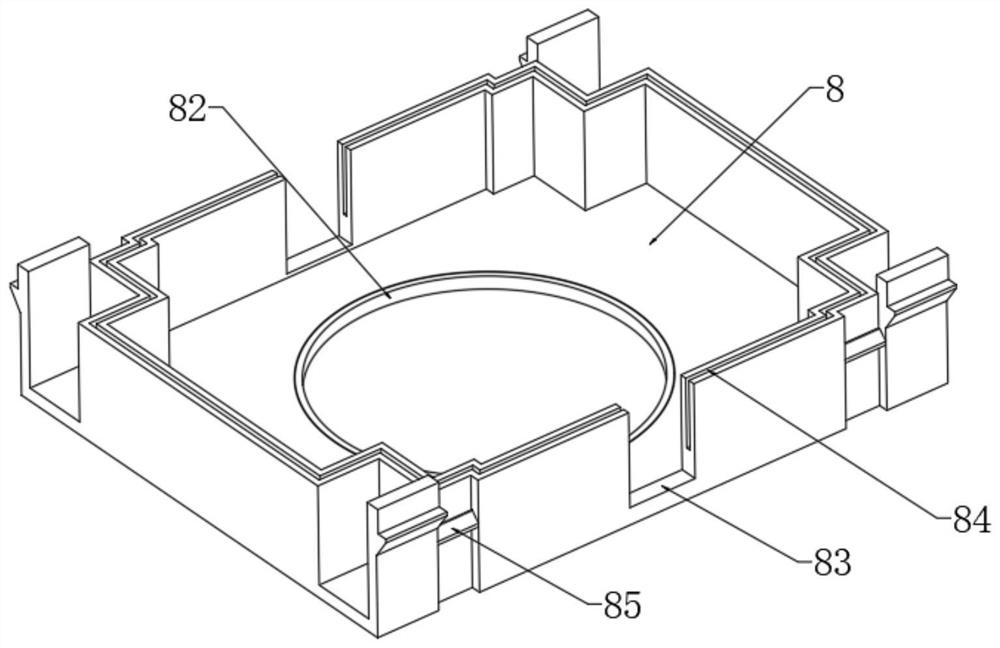
[0029] see Figure 1 to Figure 8 , the present invention provides a technical solution: a point light source with a controllable light lens, including a back cover 1, a PCBA board 4, a lens 7 and a front cover 8, the upper end of the back cover 1 is integrally formed with a sealing edge 11, and the back cover The left and right sides of the 1 are welded with an external buckle 2 symmetrically, the upper end of the back cover 1 is welded with a pair of inner bu...


PUM


Abstract

The invention relates to the technical field of point light sources, in particular to a point light source with a controllable light lens. The point light source comprises a rear cover, a PCBA (Printed Circuit Board Assembly), a lens and a front cover, a sealing edge is integrally formed at the upper end of the rear cover, a pair of outer buckles are symmetrically welded on the left and right sides of the rear cover, a pair of inner buckles are symmetrically welded on the left and right sides of the upper end of the rear cover, a pair of limiting plates are symmetrically welded to the front portion and the rear portion of the upper end of the rear cover, and a pair of cylinders are symmetrically welded to the positions, on the inner sides of the limiting plates, of the upper end of the rear cover. The point light source has the beneficial effects that: by rotating a rotary knob, a threaded rod rotates, the threaded rod drives two nuts to move, the nuts drive a bottom plate to move, the bottom plate drives a concave block to move, the concave block pushes a movable plate to rotate, and the movable plate drives a transverse plate and a point light source lamp to move, so that the light emitting angle of the point light source lamp is adjusted. The point light source assembly is connected with the rear cover in a clamped mode, the movable plate in a lamp body mechanism is connected with a concave plate in an adjusting mechanism, and therefore the adjusting mechanism can adjust the angle of the point light source lamp.

Description

technical field [0001] The invention relates to the technical field of point light sources, in particular to a point light source with a controllable light lens. Background technique [0002] LED point light sources are generally combined and arranged according to different rules to form different overall effects. They are widely used in bridges, rivers, gardens, buildings, lampposts, etc., to highlight their outlines and achieve the effect of beautifying decoration; The light source basically adopts LED lamp beads with a cover optical lens (commonly known as lampshade), which has low energy consumption and good luminous effect. The front cover and the lens of the existing LED point light source are fixedly connected by welding or pasting, and the front cover and the rear cover are fixed by bolts. When assembling the LED point light source, the front cover and the lens need to be precisely matched, and then fixedly connected by welding or pasting equipment, which not only i...

Claims


Application Information

Patent Timeline
Patent Type & Authority Applications(China)
IPC IPC(8): F21S8/00F21V17/10F21V19/02F21V31/00F21Y115/10
CPCF21S8/00F21V17/105F21V31/005F21V19/02F21Y2115/10Y02B20/40
Inventor 戴瑞
Owner 安徽睿翔光电科技有限公司
Learn More