Suspension motor rotor suspension position, deflection angle and rotating speed integrated detection system and application

A technology of deflection angle and motor rotor, applied in the direction of measuring devices, instruments, etc., can solve the problems of low resolution, complex structure of rotor detection device, poor measurement position and speed detection accuracy, etc., to eliminate common mode interference and improve speed detection Accuracy and sensitivity, the effect of improving detection accuracy and sensitivity

Active Publication Date: 2021-10-29
SHANDONG UNIV +1
View PDF5 Cites 0 Cited by
  • Summary
  • Abstract
  • Description
  • Claims
  • Application Information

AI Technical Summary

Problems solved by technology

[0008] Aiming at the deficiencies of the prior art, the present invention provides an integrated detection system for the levitation position, deflection angle and rotational speed of the rotor of the suspended motor, which overcomes the complex structure of the rotor detection device, poor detection accuracy of the measurement position and rotational speed, and low resolution in the prior art. technical problem

Method used


Image

  • Suspension motor rotor suspension position, deflection angle and rotating speed integrated detection system and application
  • Suspension motor rotor suspension position, deflection angle and rotating speed integrated detection system and application
  • Suspension motor rotor suspension position, deflection angle and rotating speed integrated detection system and application

Examples


Embodiment 1

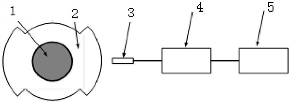
[0048] Such as Figure 2-3 As shown, this embodiment provides an integrated detection system for the suspension position, deflection angle and rotational speed of the rotor of a suspension motor, including a radial test piece 2, an eddy current sensor 3, a front processor 4 and a processor 5, wherein the eddy current sensor 3 is connected with a front-end device 4, and the front-end device 4 is connected with a processor 5, the front-end device 4 is used to supply power to the eddy current sensor 3 and detect and analyze the circuit, and the processor 5 is used to process the measurement results of the eddy current sensor and eliminate the rotor Influence of radial suspension position eccentricity on detection result accuracy.

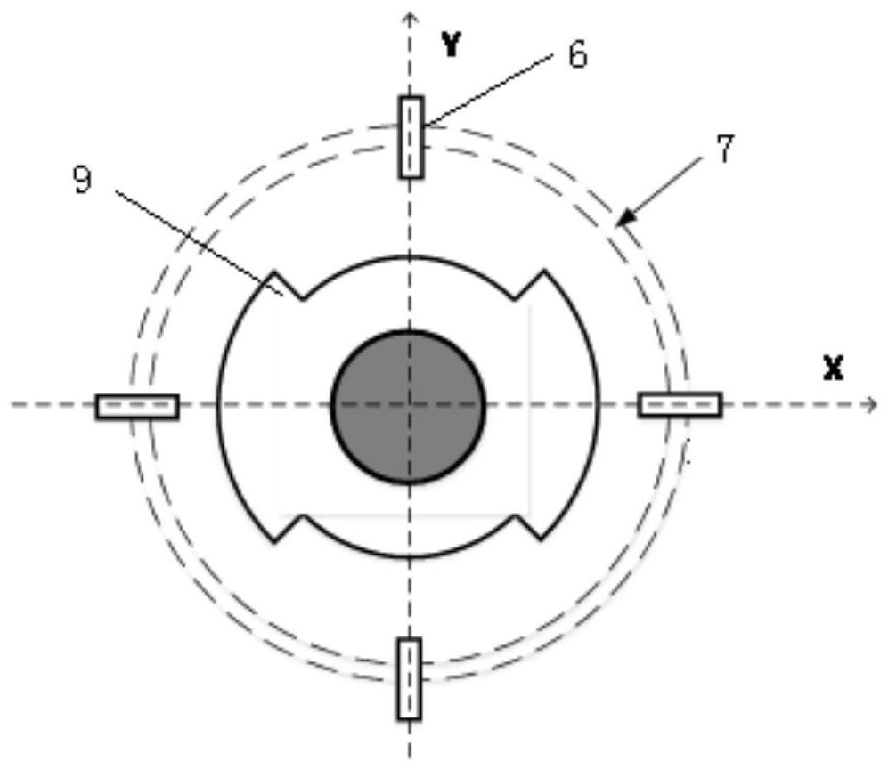
[0049] The radial test piece 2 includes an annular cylinder, and the outer symmetrical protrusion of the annular cylinder is provided with an arc segment 9, and the arc segment is concentric with the annular cylinder.

[0050] There are at least 2 arc...

Embodiment 2

[0067] An application of an integrated detection system for the suspension position, deflection angle and rotational speed of the rotor of a suspension motor. The operation steps are as described in Embodiment 1. The difference is that the zero adjustment tooling 8 includes a hollow cylinder with an open end, and the bottom of the hollow cylinder is A cylinder is set at the center, such as Figure 4 As shown, the inner diameter of the hollow cylinder is the same as the outer diameter of the annular shell, and it is used to fix the annular shell. The diameter of the cylinder is the same as that of the rotor shaft. The center position of the radial test piece is the same as the center position during work, so as to adjust the zero position of the eddy current sensor.

Embodiment 3

[0069] An application of an integrated detection system for the levitation position, deflection angle, and rotational speed of the rotor of a levitation motor. The operation steps are as described in Embodiment 1. The difference is that in step (1), four eddy current sensors are respectively arranged at both ends of the rotor. , determine the axial installation distance L of the eddy current sensors at both ends, and the ratio of the displacement difference (y1-y2) measured by the eddy current sensors in the corresponding directions at both ends to the axial installation distance (L) is the rotor deflection angle in this direction The tangent value tanα, the arctangent calculation can get the deflection angle α of the rotor, the calculation principle diagram is as follows Figure 10 shown.


PUM


Abstract

The invention relates to a suspension motor rotor suspension position, deflection angle and rotating speed integrated detection system and application, and belongs to the technical field of detection instruments. The system comprises a radial test piece, an eddy current sensor, a front-end device and a processor, the eddy current sensor is connected with the front-end device, the front-end device is connected with the processor, the front-end device is used for supplying power to the eddy current sensor and detecting an analysis circuit, and the processor is used for processing a measurement result of the eddy current sensor. The technical problems that a rotor detection device in the prior art is complex in structure, poor in measurement position and rotation speed detection precision and low in resolution are solved.

Description

technical field [0001] The invention relates to an integrated detection system for the suspension position, deflection angle and rotational speed of a suspension motor rotor and its application, belonging to the technical field of detection instruments. Background technique [0002] The suspension motor has the advantage of no mechanical friction, which is more conducive to high-speed and efficient operation. The stable and reliable operation of the active levitation motor requires real-time detection and closed-loop control of the radial levitation position and rotational speed of the rotor (even if the control method without speed sensor is adopted, the algorithm debugging stage still needs external speed sensor auxiliary verification). At present, the detection of rotor radial vibration (position) usually uses capacitive, inductive and eddy current sensors, and usually only detects the vibration in one direction of x or y (ignoring the vibration and displacement in the or...

Claims


Application Information

Patent Timeline
Patent Type & Authority Applications(China)
IPC IPC(8): G01D21/02
CPCG01D21/02
Inventor 王丽俞军涛王松李雪莲王挺侹宋玉美
Owner SHANDONG UNIV
Why Eureka
Try Eureka