
Laser radar orthogonal receiving and transmitting system based on discrete adjustable grating

A laser radar, transceiver system technology, applied in radio wave measurement systems, instruments, etc., can solve the problems of limited radiation width, unfavorable mass production, too large waveguide spacing, etc., to optimize the strip radiation pattern and reduce the number of phase shifters , the effect of reducing the difficulty of control

Active Publication Date: 2021-10-29
长沙思木锐信息技术有限公司
View PDF4 Cites 2 Cited by
  • Summary
  • Abstract
  • Description
  • Claims
  • Application Information

AI Technical Summary

Problems solved by technology

Traditional mechanical scanning is expensive and not conducive to mass production; the existing LiDAR solid-state two-dimensional scanning requires an N×N phase shifter array, and with the improvement of measurement accuracy and area, the number of phase shifters will be significantly increased. increases, which can cause difficulties in manufacturing and signal configuration
[0004] Although the use of the orthogonal transceiver lidar system can reduce the N×N phase shifter array required by the original solid-state two-dimensional scanning of the lidar to 2N, but the scanning by the general on-chip phased array method will cause problems due to waveguide The grating lobe is generated when the spacing is too large; although this scanning problem can be solved by means of a wide-body surface grating, the obtained strip radiation pattern is not very uniform, and the radiation width is relatively limited, and parallel reception cannot be performed.

Method used


Image

  • Laser radar orthogonal receiving and transmitting system based on discrete adjustable grating
  • Laser radar orthogonal receiving and transmitting system based on discrete adjustable grating
  • Laser radar orthogonal receiving and transmitting system based on discrete adjustable grating

Examples


Embodiment Construction

[0069] The following will clearly and completely describe the technical solutions in the embodiments of the present invention with reference to the accompanying drawings in the embodiments of the present invention. Obviously, the described embodiments are only some, not all, embodiments of the present invention. Based on the embodiments of the present invention, all other embodiments obtained by persons of ordinary skill in the art without making creative efforts belong to the protection scope of the present invention.

[0070] In order to make the above objects, features and advantages of the present invention more comprehensible, the present invention will be further described in detail below in conjunction with the accompanying drawings and specific embodiments.

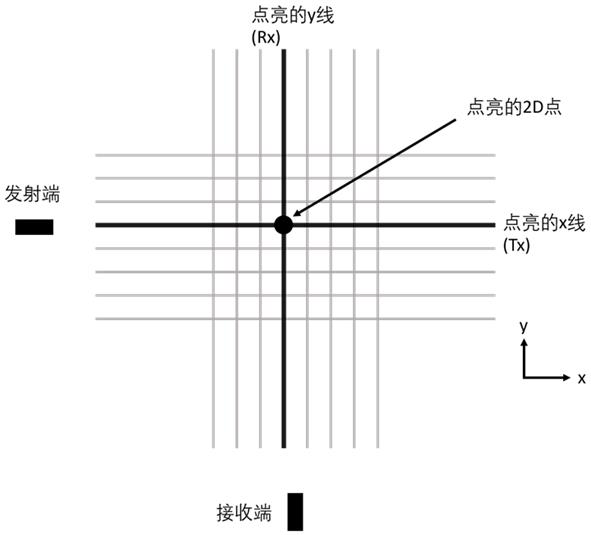
[0071] refer to figure 1 , figure 1 It is a schematic diagram of the basic principle of a laser radar orthogonal transceiver system provided by an embodiment of the present invention.

[0072] The laser radar or...


PUM


Abstract

The invention provides a laser radar orthogonal receiving and transmitting system based on a discrete adjustable grating. The laser radar orthogonal receiving and transmitting system comprises a transmitting unit and a receiving unit, wherein the transmitting unit transmits light wave signals in a specific far-field radiation pattern along a first direction, and scans in a second direction; the receiving unit receives an optical detection signal which is transmitted by the transmitting unit and is reflected by an object to be detected along the second direction, and scans in the first direction; and the first direction is perpendicular to the second direction, wherein the transmitting unit and / or the receiving unit comprise / comprises a surface grating array formed by a plurality of surface gratings. According to the laser radar orthogonal receiving and transmitting system, the surface grating array of the discrete adjustable grating is adopted to replace a continuous adjustable phased array grating, so that the laser radar orthogonal receiving and transmitting system is simple in structure.

Description

technical field [0001] The invention relates to the technical field of laser radar, more specifically, to a laser radar orthogonal transceiver system based on a discrete adjustable grating. Background technique [0002] Lidar technology is widely used in fields such as ground exploration, archaeology, and autonomous driving. [0003] At present, lidar scanning technology can be roughly divided into two categories: mechanical scanning and solid-state scanning. Traditional mechanical scanning is expensive and not conducive to mass production; the existing LiDAR solid-state two-dimensional scanning requires an N×N phase shifter array, and with the improvement of measurement accuracy and area, the number of phase shifters will be significantly increased. Increase, will cause difficulties in manufacturing and signal configuration. [0004] Although the use of the orthogonal transceiver lidar system can reduce the N×N phase shifter array required by the original solid-state two-...

Claims


Application Information

Patent Timeline
IPC IPC(8): G01S7/4911G01S7/4913
CPCG01S7/4911G01S7/4913
Inventor 张璟
Owner 长沙思木锐信息技术有限公司
Learn More