Broadband sound absorber of low-pass sound filter bank
A filter bank and filter technology, applied in the direction of sound-producing equipment, instruments, etc., can solve the problems of difficult design and poor low-frequency sound absorption effect.
- Summary
- Abstract
- Description
- Claims
- Application Information
AI Technical Summary
Problems solved by technology
Method used
Image

Examples
Embodiment 1
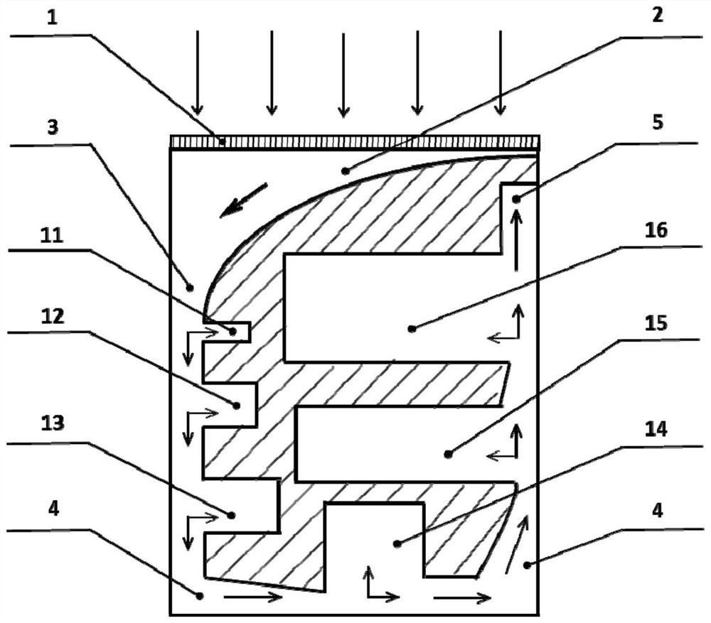
[0044]Embodiment 1: as figure 1 shown
[0045] The low-pass acoustic filter bank broadband sound absorber consists of a micro-perforated plate 1, a cavity 2 behind the micro-perforated plate, a meandering sound wave main channel 4 communicating with the plate back cavity 2, and a main meandering sound wave channel 4 arranged along the meandering sound wave main channel 4. Low-pass acoustic filter bank composition;
[0046] The micro-perforated plate 1 has an external sound wave incident end on one side, and a cavity 2 is arranged on the other side. The cavity 2 is surrounded by side walls. The volume of the cavity 2 is calculated according to the area of the micro-perforated plate 1 multiplied by its perforation Estimated by the numerical results of the rate, the end of the cavity 2 is connected to the beginning 3 of the main acoustic channel; the external incident sound wave enters the subsequent cavity 2 through the micro-perforated plate 1, and then enters the main acous...
Embodiment 2
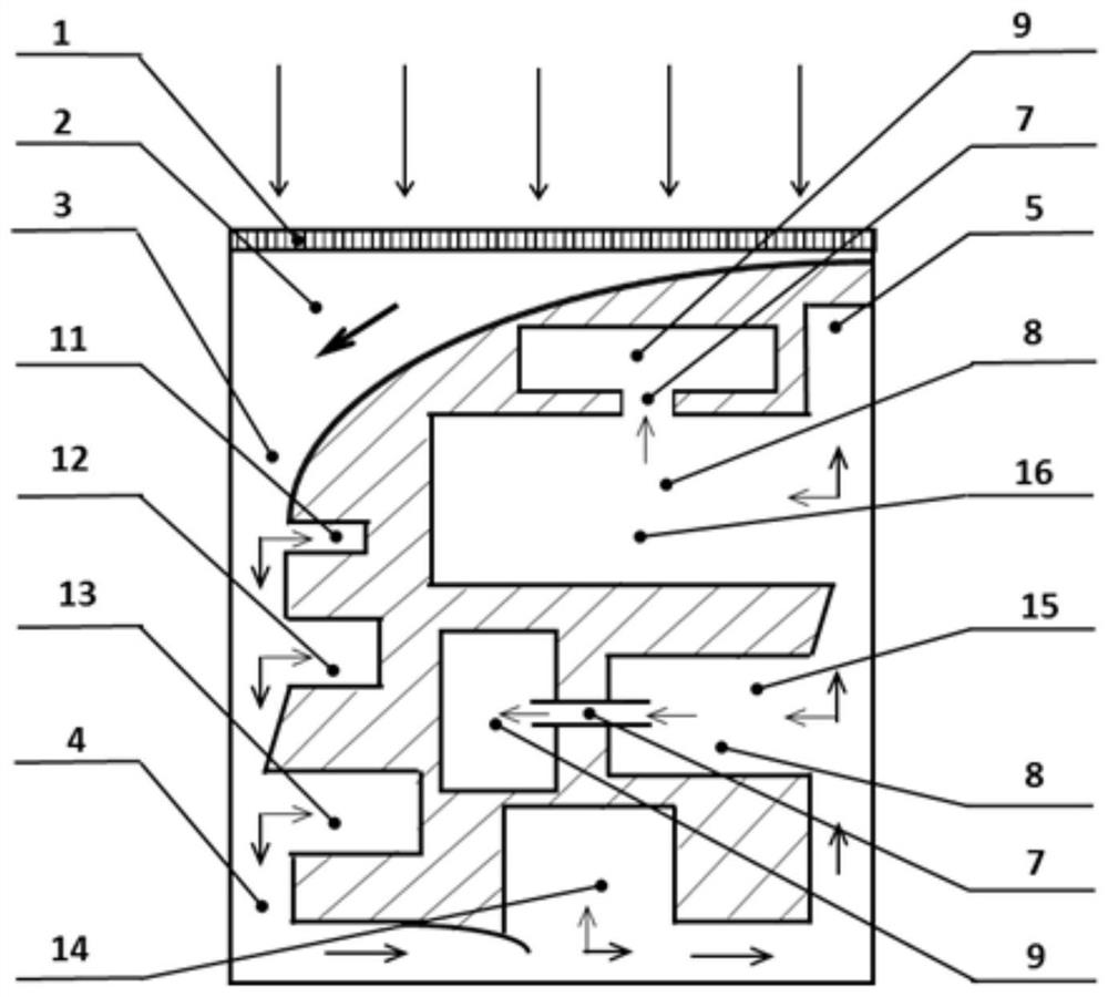
[0051] Embodiment 2: as figure 2 shown
[0052] Embodiment 2 is basically the same as Embodiment 1, the main difference is:
[0053] The low-pass acoustic filter 13 is composed of a single cavity and a section of variable-section acoustic wave main channel communicated with the cavity;
[0054] The low-pass acoustic filter 14 is composed of a single cavity and a section of variable-section sound wave main channel communicated with the cavity, and the variable-section sound wave main channel extends to the inside of the cavity;
[0055] The low-pass acoustic filter 15 is composed of an interface cavity 8, an auxiliary cavity 9, a thin branch tube 7 communicating with the double cavities 8 and 9, and a section of equal-section sound wave main channel communicated with the interface cavity 8, and the thin branch tube 7 extends into the cavity;
[0056] The low-pass acoustic filter 16 is composed of an interface cavity 8, an auxiliary cavity 9, a thin branch tube 7 communicati...
Embodiment 3
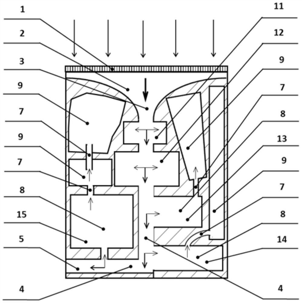
[0058] Embodiment 3: as image 3 shown
[0059] The low-pass acoustic filter bank broadband sound absorber consists of a micro-perforated plate 1, a cavity 2 behind the micro-perforated plate, a meandering sound wave main channel 4 communicating with the plate back cavity 2, and a main meandering sound wave channel 4 arranged along the meandering sound wave main channel 4. Low-pass acoustic filter bank composition;
[0060] The micro-perforated plate 1 has an external sound wave incident end on one side, and a cavity 2 is arranged on the other side. The cavity 2 is surrounded by side walls. The volume of the cavity 2 is calculated according to the area of the micro-perforated plate 1 multiplied by its perforation Estimated by the numerical results of the rate, the end of the cavity 2 is connected to the beginning 3 of the main acoustic channel; the external incident sound wave enters the subsequent cavity 2 through the micro-perforated plate 1, and then enters the main acou...
PUM
 Abstract
Description
Claims
Application Information