Eureka AIR delivers breakthrough ideas for toughest innovation challenges, trusted by R&D personnel around the world.

Multi-finger transistor and power amplifier circuit

A transistor and electrical connection technology, applied in the field of multi-finger transistors and power amplifier circuits, can solve the problems of inability to obtain amplification characteristics, uneven action, etc.

Pending Publication Date: 2021-10-29
MURATA MFG CO LTD
View PDF1 Cites 0 Cited by
  • Summary
  • Abstract
  • Description
  • Claims
  • Application Information

AI Technical Summary

Problems solved by technology

As a result, a plurality of unit transistors operate unevenly
If a plurality of unit transistors operate unevenly, desired amplification characteristics cannot be obtained

Method used


Image

  • Multi-finger transistor and power amplifier circuit
  • Multi-finger transistor and power amplifier circuit
  • Multi-finger transistor and power amplifier circuit

Examples


no. 1 Embodiment approach and comparative example

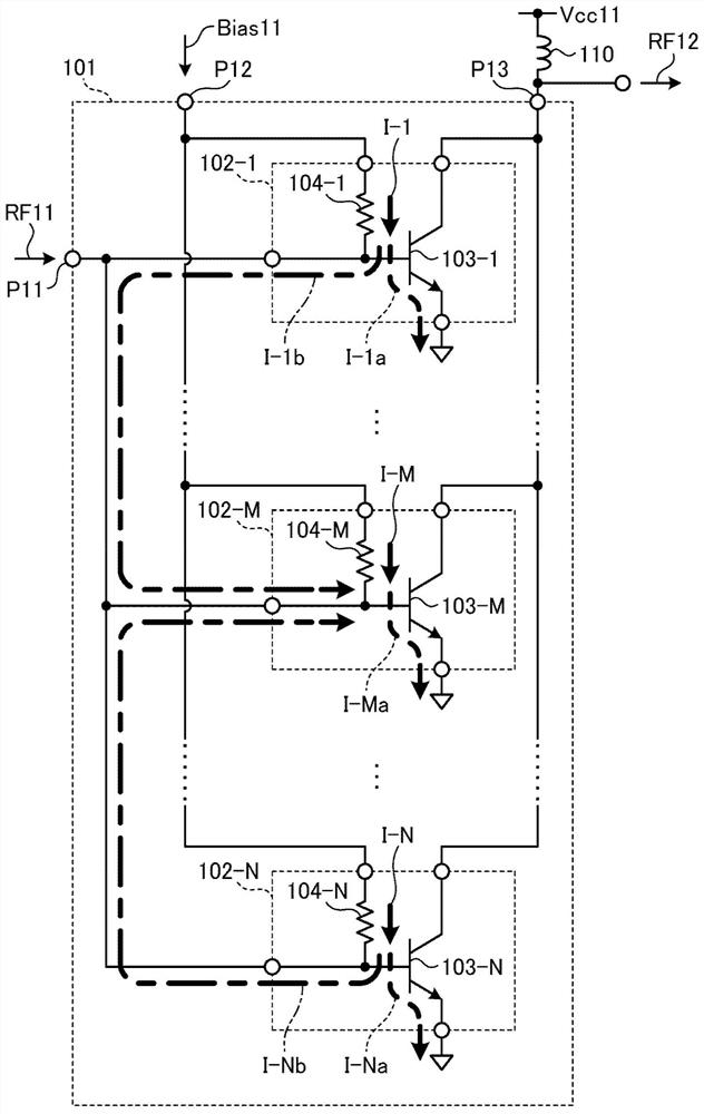
[0027] Hereinafter, the first embodiment will be described, but in order to make the first embodiment easier to understand, a comparative example will be described first.

no. 1 Embodiment approach

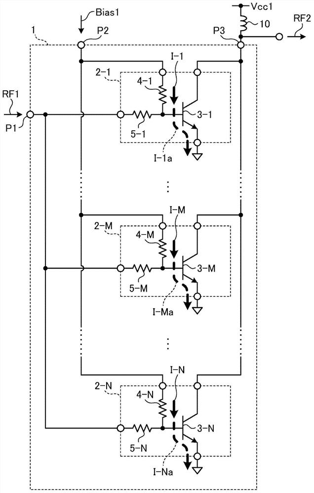
[0044] figure 2 It is a figure showing the structure of the multi-finger transistor of 1st Embodiment. The multi-finger transistor 1 is formed by electrically connecting a plurality of unit transistors in parallel. A unit transistor refers to a minimum structure constituting a transistor.

[0045] The finger transistor 1 has a first terminal P1 to which an AC signal RF1 is input, a second terminal P2 to which a bias current Bias1 is input, and a third terminal P3 to which an AC signal RF2 is output. The third terminal P3 is electrically connected to the power supply potential Vcc1 via the choke inductor 10 .

[0046] The first terminal P1 corresponds to an example of the "common input terminal" in the present disclosure. The second terminal P2 corresponds to an example of the "common bias terminal" in the present disclosure. The third terminal P3 corresponds to an example of the "common output terminal" in the present disclosure.

[0047]The multi-finger transistor 1 is ...

no. 2 Embodiment approach

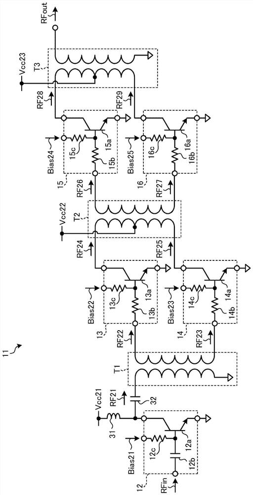
[0063] image 3 It is a figure which shows the structure of the power amplifier circuit of 2nd Embodiment. in detail, image 3 It is a diagram showing the configuration of a power amplifying circuit to which the multi-finger transistor 1 of the first embodiment is applied.

[0064] The power amplifying circuit 11 may be realized by a hybrid IC (also referred to as a module) in which a plurality of components (semiconductor chips, etc.) are mounted on one substrate, but the present disclosure is not limited thereto.

[0065] The power amplifying circuit 11 includes a multi-finger transistor 12 as a first-stage power amplifier, multi-finger transistors 13 and 14 as a second-stage power amplifier, and multi-finger transistors 15 and 16 as a third-stage power amplifier. In addition, the number of stages of the power amplifier is not limited to three, and may be two or less or four or more.

[0066] The multi-finger transistor 12 is a general multi-finger transistor in which a D...


PUM


Abstract

The invention provides a multi-finger transistor and a power amplifier circuit, which enable a plurality of unit transistors to operate uniformly. The present invention includes: a plurality of unit transistors each including a first terminal electrically connected to a reference potential, a second terminal to which a high-frequency signal and a bias current are input, and a third terminal to which an amplified signal obtained by amplifying the high-frequency signal is output; a common input terminal which electrically connects the second terminals of the plurality of unit transistors in parallel and to which a high-frequency signal is input; a common bias terminal which electrically connects the second terminals of the plurality of unit transistors in parallel and to which a bias current is input; a common output terminal which electrically connects the third terminals of the plurality of unit transistors in parallel and outputs an amplified signal; and a plurality of first resistance elements which are electrically connected between the second terminals of the plurality of unit transistors and the common input terminal, respectively, and which cut off the DC component of the bias current.

Description

technical field [0001] The invention relates to a multi-finger transistor and a power amplifier circuit. Background technique [0002] Patent Document 1 describes a power amplifier module using transistors. In Patent Document 1, an AC signal is input to the base of the transistor without passing through a DC cutoff capacitor. [0003] prior art literature [0004] patent documents [0005] Patent Document 1: International Publication No. 2015 / 001851 [0006] In an amplifier circuit, multi-finger transistors in which a plurality of unit transistors (also referred to as fingers) are electrically connected in parallel may be used. A unit transistor refers to a minimum structure constituting a transistor. In addition, the multi-finger transistor in the present disclosure is defined as connecting a plurality of unit transistors in parallel to function as one transistor circuit, and the number of emitters is plural. [0007] If the bases of a plurality of unit transistors ar...

Claims


Application Information

Patent Timeline
Patent Type & Authority Applications(China)
IPC IPC(8): H03F3/20
CPCH03F3/20H03F3/245H03F3/195H03F2200/451H03F3/211H03F2200/534H03F2200/537H03F2200/541
Inventor 柳原真悟
Owner MURATA MFG CO LTD
Why Eureka
Eureka Blog
Learn More