

time measurement circuit
A time measurement and circuit technology, applied in the direction of electrical unknown time interval measurement, time interval measurement devices, clocks, etc., can solve problems such as the inability to meet product technical requirements, and achieve the effect of accurate time measurement and low power consumption action
- Summary
- Abstract
- Description
- Claims
- Application Information
AI Technical Summary
Problems solved by technology
Method used
Image

Examples
no. 1 Embodiment
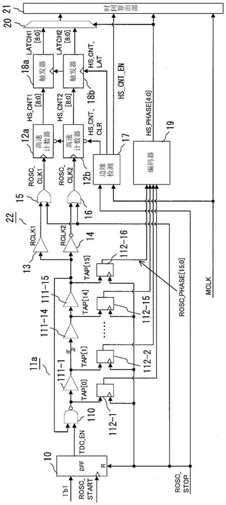
[0064] Hereinafter, embodiments of the present invention will be described with reference to the accompanying drawings. figure 1It is a circuit diagram showing the configuration of the time measuring circuit according to the first embodiment of the present invention. The time measurement circuit includes a D flip-flop circuit 10 that uses a 1-bit binary number "1" (1'b1) as a D input, uses an external oscillation start signal ROSC_START as a clock input, and uses an external oscillation stop signal ROSC_STOP For reset input, the oscillation permission signal TDC_EN is output; the ring oscillator 11a (oscillation circuit), which generates the high-speed clock TAP[15] (first clock) during the period when the oscillation permission signal TDC_EN is valid; the buffer circuit 13, which uses the high-speed clock TAP[15] is the input and outputs the high-speed clock RCLK1 (the first clock); the inverter 14 outputs the high-speed clock RCLK2 (the second clock) obtained by inverting t...
no. 2 Embodiment
[0101] Next, a second embodiment of the present invention will be described. In the first embodiment, the signal RCLK1 obtained by passing the high-speed clock TAP[15] output from the ring oscillator 11a through the buffer circuit 13 is obtained by logically inverting the high-speed clock TAP[15] by the inverter 14. Both signals RCLK2 are masked by the oscillation stop signal ROSC_STOP, but instead of the inverted signal output from the ring oscillator 11a, a signal that does not mask the high-speed clock TAP[15] output from the ring oscillator 11a may be prepared and For the masked signal, each signal is counted by different high-speed counters, and then the count result obtained by the high-speed counter that does not generate a false signal is selected.
[0102] Figure 10 In order to show the circuit diagram of the configuration of the time measurement circuit of this embodiment, figure 1 The same components are marked with the same symbols. The time measurement circui...
no. 3 Embodiment
[0121] Next, a third embodiment of the present invention will be described. Figure 17 In order to show the circuit diagram of the configuration of the time measurement circuit of this embodiment, figure 1 , Figure 10 The same components are marked with the same symbols. The time measurement circuit of this embodiment includes a D flip-flop circuit 10, a ring oscillator 11a (oscillation circuit), high-speed counters 12a, 12b (first counter, second counter), a buffer circuit 13, an inverter 14, and an edge detection circuit 17a, D flip-flop circuits 18a, 18b, encoder 19, selector 20, time calculation unit 21a, and operation setting circuit 24 that selects and outputs an oscillation start signal ROSC_START ( The first start signal), the oscillation stop signal ROSC_STOP (the first stop signal), and the start signal DBG_START (the second start signal) and the stop signal DBG_STOP (the second start signal) and the stop signal DBG_STOP (the second start signal) output from the ...
PUM
 Abstract
Description
Claims
Application Information