Differential case drilling clamp

A technology of differential case and drilling jig, which is applied in the direction of clamping, manufacturing tools, supports, etc., which can solve the problems of complex jig structure and inability to eliminate the press fit gap, and achieve the effect of reducing labor intensity and working hours

Pending Publication Date: 2021-11-02
TIANRUN IND TECH CO LTD +1
View PDF1 Cites 0 Cited by
  • Summary
  • Abstract
  • Description
  • Claims
  • Application Information

AI Technical Summary

Problems solved by technology

[0005] The purpose of the present invention is to solve the technical problem that the existing clamp structure is complex and cannot eliminate the press fit gap, and to provide a differential housing drilling clamp with reasonable structure, convenient operation, and applicable to horizontal machining centers and special equipment

Method used


Image

  • Differential case drilling clamp
  • Differential case drilling clamp
  • Differential case drilling clamp

Examples


Embodiment Construction

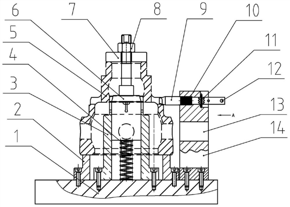
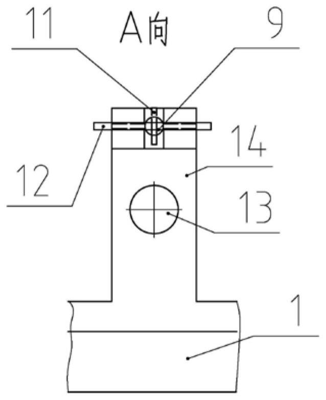
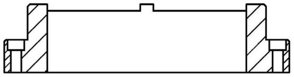
[0023] Such as figure 1 As shown in ~3, the present invention provides a differential case drilling jig, which is provided with a base 1, a support seat 2, an expansion spring 3, a compression spring A4, a differential case 5, an expansion cone 6, and an opening ring 7 , Compression nut 8, positioning pin 9, compression spring B10, stop pin 11, handle 12, let the knife hole 13, positioning seat 14.

[0024] The base 1 is a square body, on which there are screw holes for installing various parts. The expansion spring 3 is provided with a sleeve with a through-hole flange on the lower part, and the inner cone with 3-4 open slots is provided on the upper part. The expansion cone 6 is the upper part. Set thread, the lower part is equipped with outer cone and stepped cylinder tie rod, the expansion cone 6 is installed in the expansion spring 3 hole, the lower end is set with the compression spring A4, and fixed with the corresponding screw hole of the base 1 through the flange hole...


PUM


Abstract

The invention relates to a differential case drilling clamp which solves the technical problems that an existing clamp is complex in structure and cannot eliminate pressing fit clearance. The differential case drilling clamp is provided with a base, an expansion spring, an expansion cone, a compression spring A, a compression spring B and a cutter relieving hole, wherein the expansion spring is in an inner cone shape, the lower part of the expansion spring is provided with a sleeve with a through hole flange, and the upper part of the expansion spring is provided with an open groove; the expansion cone is sequentially provided with a screw rod, a small cylinder, an outer cone, a cylinder and a short cylinder from top to bottom; the outer cone of the expansion cone is matched with the inner cone of the expansion spring, and the outer circle of the expansion spring tightly presses a differential case by force generated by rotation of a compression nut on the screw rod arranged on the expansion cone so that the correct position of a machined hole can be ensured; and the short cylinder of the expansion cone is sleeved with the compression spring A. The differential case drilling clamp can be used in the field of differential case machining.

Description

technical field [0001] The invention relates to a jig, in particular to a drilling jig for a differential case. Background technique [0002] The differential of a car is a device that forms a speed difference. It has four holes for installing drive shafts and requires the two output shafts to always output the same torque. Accuracy requirements are more stringent. [0003] The Chinese invention patent application with the publication number CN109514289A discloses a differential case drilling jig, including thickened nuts, formwork, positioning discs, limit blocks, support blocks, diamond pins, opening pads, guide posts, templates , Press block, small end guide bush, middle guide bush, big end guide bush, bushing, pin shaft, pin spring, handle, bracket, positioning key, cover plate, transmission shaft, tapered roller bearing, flange, skeleton Oil seal, oil seal flange, rotary table body, rotary table, pressure plate, pressure plate gasket, compression spring, long screw, s...

Claims


Application Information

Patent Timeline
IPC IPC(8): B23Q3/06
CPCB23Q3/06B23Q3/062
Inventor 王磊侯珍夏永平徐洪波李百序
Owner TIANRUN IND TECH CO LTD
Why Eureka
Try Eureka