Decoration plate abutted seam cracking reinforcing structure device
A technology of jointing and construction, applied in building construction, building maintenance, manufacturing tools, etc., can solve the problems of reducing the service life of the board, easy to corrode the board, easy to crack, etc., to increase the toughness, increase the service life, and improve the work. The effect of efficiency
- Summary
- Abstract
- Description
- Claims
- Application Information
AI Technical Summary
Problems solved by technology
Method used
Image
Examples
Embodiment 1
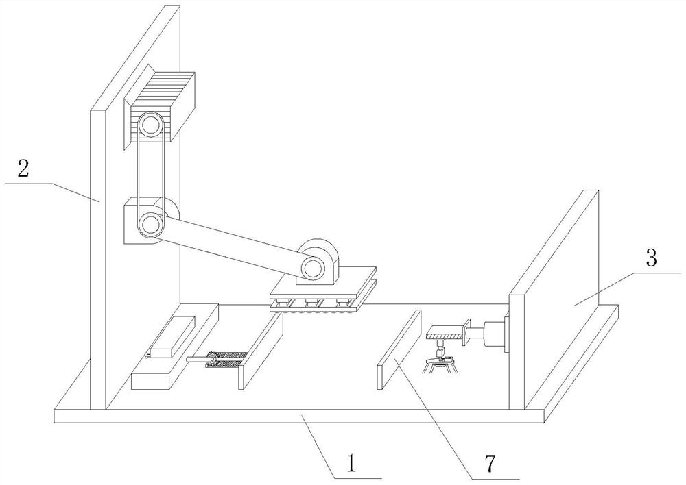
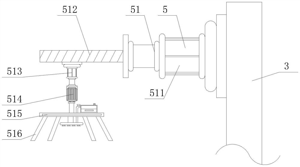
[0047] like Figure 1-6 As shown in the figure, the present invention provides a joint cracking reinforcement structure device for decorative panels, including a base 1, a support plate 2 and a connecting plate 3, the left side of the top of the base 1 is fixedly connected with the support plate 2, and the right side of the top of the base 1 is fixed A connecting plate 3 is connected, a cleaning device 5 is fixedly connected to the top of the left side of the connecting plate 3, a fixing device 4 is fixedly connected to the top of the right side of the support plate 2, and the cleaning device 5 includes a cleaning device 51, and the right side of the cleaning device 51 is fixed Connected to the top of the left side of the connecting plate 3, the bottom of the cleaning device 51 is fixedly connected with a dust suction device 52, the fixing device 4 includes a No. 1 motor 41, and one side of the No. 1 motor 41 is fixedly connected to the top of the right side of the support plat...
Embodiment 2
[0051] like Figure 1-6 As shown, on the basis of Embodiment 1, the present invention provides a technical solution: preferably, a clamping device 6 is fixedly connected to the left side of the top of the base 1, and the clamping device 6 includes a piston cylinder 61, and the inner wall of the piston cylinder 61 is fixedly connected. A heater 62 is fixedly connected to the left side of the piston cylinder 61, a piston plate 63 is movably sleeved inside the piston cylinder 61, a connecting rod 64 is fixedly connected to one side of the piston plate 63, and one end of the connecting rod 64 extends to the outside of the piston cylinder 61 and is movable A gear 65 is connected, the bottom of the gear 65 is engaged with a rack 66, the bottom of the rack 66 is fixedly connected to the top of the base 1, one side of the gear 65 is movably connected with a push rod 67, and one end of the push rod 67 is fixedly connected with a push rod. Plate 68, the bottom of the push plate 68 overl...
Embodiment 3
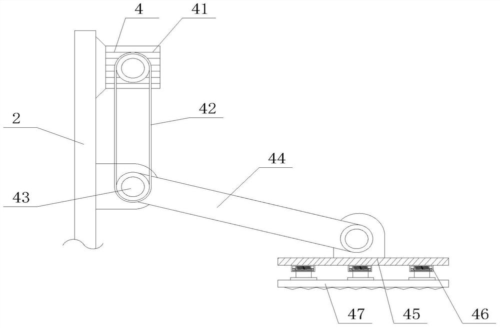
[0054] like Figure 1-6 As shown, on the basis of Embodiment 1, the present invention provides a technical solution: preferably, the output end of the No. 1 motor 41 is rotatably connected with a crawler 42, and the bottom of the inner wall of the crawler 42 is rotatably connected with a movable shaft 43, and the movable shaft 43 One end of the movable shaft 43 is movably sleeved inside the support plate 2, the outer wall of the movable shaft 43 is fixedly connected with a movable rod 44, one end of the movable rod 44 is movably connected with a fixed plate 45, and the bottom of the fixed plate 45 is fixedly connected with a buffer device 46, the buffer device The bottom of 46 is fixedly connected with a pressure plate 47, and the bottom of the pressure plate 47 is provided with anti-skid lines.
[0055] In this embodiment, the No. 1 motor 41 drives the crawler 42, the movable shaft 43 and the movable rod 44 to rotate, and the movable rod 44 drives the pressing plate 47 to com...
PUM
 Abstract
Description
Claims
Application Information
 - R&D
- Intellectual Property
- Life Sciences
- Materials
- Tech Scout
- Unparalleled Data Quality
- Higher Quality Content
- 60% Fewer Hallucinations
Browse by: Latest US Patents, China's latest patents, Technical Efficacy Thesaurus, Application Domain, Technology Topic, Popular Technical Reports.
© 2025 PatSnap. All rights reserved.Legal|Privacy policy|Modern Slavery Act Transparency Statement|Sitemap|About US| Contact US: help@patsnap.com


