Main hoisting mechanism of metallurgical ladle crane

A lifting mechanism and crane technology, which is applied to cranes, trolley cranes, traveling mechanisms, etc., can solve problems such as loud noise, low transmission efficiency, and poor precision, and achieve high transmission efficiency, reduced slippage, and low noise. Effect

Pending Publication Date: 2021-11-02
安徽江河智能装备集团有限公司
View PDF1 Cites 0 Cited by
  • Summary
  • Abstract
  • Description
  • Claims
  • Application Information

AI Technical Summary

Problems solved by technology

[0003] For example, the patent publication number is CN109775575A, which discloses a kind of bridge crane, including a crane girder, the middle guide of the crane girder is equipped with a movable seat, and the two ends of the crane girder are respectively provided with sliding seats that cooperate with the track. The bottom end of the outer side of the slide seat is equipped with a power sprocket, and guide grooves corresponding to the position of the power sprocket are respectively arranged on the track, and a rack is laid in the guide groove, and guide rollers are respectively installed at the front and rear ends of the power sprocket, and the slide seat There is an L-shaped guide rod at the bottom end of the inner side of the crane, and a roller is installed on the horizontal section of the L-shaped guide rod. The inner side of the track is provided with an outwardly protruding boss, and a transmission shaft is installed between the sliding seats on one side of the main beam of the crane. , the two ends of the transmission shaft are respectively equipped with transmission sprockets, and the power sprockets are respectively meshed with the transmission sprockets at the corresponding ends. The movable mechanism in the above device adopts chain transmission, which has the disadvantages of high noise, low transmission efficiency and poor accuracy.

Method used


Image

  • Main hoisting mechanism of metallurgical ladle crane
  • Main hoisting mechanism of metallurgical ladle crane
  • Main hoisting mechanism of metallurgical ladle crane

Examples


Embodiment Construction

[0028] The following will clearly and completely describe the technical solutions in the embodiments of the present invention with reference to the accompanying drawings in the embodiments of the present invention. Obviously, the described embodiments are only some, not all, embodiments of the present invention. Based on the embodiments of the present invention, all other embodiments obtained by persons of ordinary skill in the art without creative efforts fall within the protection scope of the present invention.

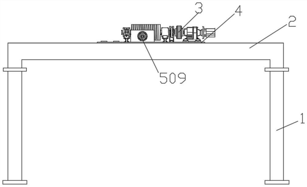
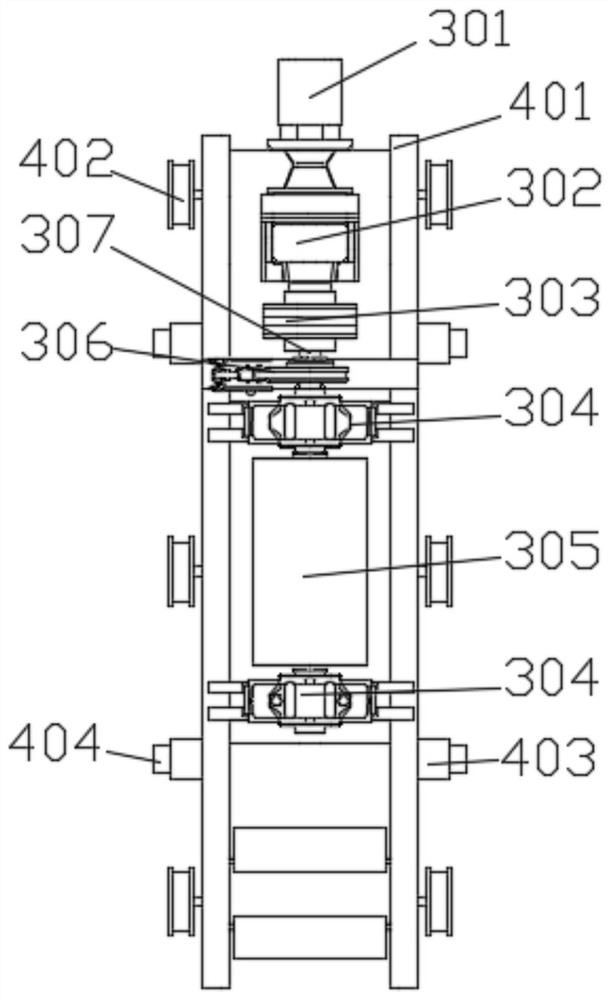
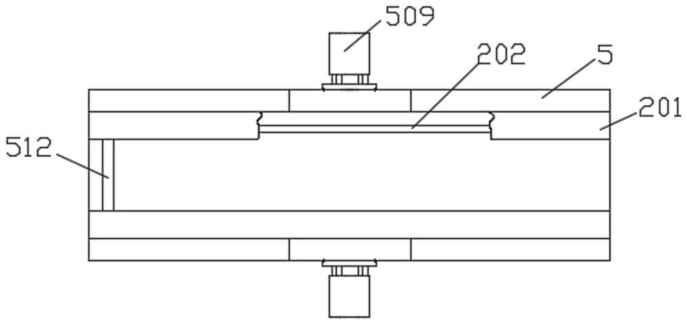
[0029] see Figure 1-6 As shown, the present invention is a main hoisting mechanism of a metallurgical casting crane, including a support frame 1, a top beam 2 is fixedly connected to the top of the support frame 1, and a transmission mechanism 5 is fixedly connected to both sides of the top beam 2 A movable frame 4 is installed between the two transmission mechanisms 5, and a lifting device 3 is fixedly connected to the top of the movable frame 4.

[0030] The tr...


PUM


Abstract

The invention discloses a main hoisting mechanism of a metallurgical ladle crane, the main hoisting mechanism of the metallurgical ladle crane comprises a support frame, wherein the top of the support frame is fixedly connected with a top beam, the two sides of the top beam are both fixedly connected with transmission mechanisms, a movable frame is installed between the two transmission mechanisms; the top of the movable frame is fixedly connected with a lifting device, a second motor drives a driving wheel to move so that a first conveying belt can rotate along with the driving wheel, the first conveying belt can be completely tensioned by adjusting the positions of two tensioning wheels; and through transmission between two gears, the friction force between the first conveying belt and the outer surface of a rolling shaft and the friction force between the second conveying belt and the outer surface of the rolling shaft are utilized, so that the movable frame integrally slides in the top beam; and meanwhile, pulleys are clamped on the sliding rails to ensure that the movement of the movable frame does not deviate; a first motor works, a rotating shaft is driven to rotate through the speed reduction effect of a speed reducer, a rotating roller installed on the rotating shaft is driven to rotate, and the lifting effect is achieved by controlling winding of a rope through the rotating roller.

Description

technical field [0001] The invention relates to the technical field of hoisting equipment, in particular to a main hoisting mechanism of a metallurgical casting crane. Background technique [0002] Metallurgical crane refers to the lifting equipment that relies on the longitudinal movement along the track direction of the workshop, the lateral movement of the trolley and the lifting movement of the hook to carry out work. [0003] For example, the patent publication number is CN109775575A, which discloses a kind of bridge crane, including a crane girder, the middle guide of the crane girder is equipped with a movable seat, and the two ends of the crane girder are respectively provided with sliding seats that cooperate with the track. The bottom end of the outer side of the slide seat is equipped with a power sprocket, and guide grooves corresponding to the position of the power sprocket are respectively arranged on the track, and a rack is laid in the guide groove, and guide...

Claims


Application Information

Patent Timeline
Patent Type & Authority Applications(China)
IPC IPC(8): B66C9/14B66C11/16B66C19/00
CPCB66C9/14B66C11/16B66C19/00
Inventor 梁大伟
Owner 安徽江河智能装备集团有限公司
Why Eureka
Try Eureka