Lightning stroke overvoltage protection device suitable for current collection line insulator in high wind speed environment
A lightning strike overvoltage and collector line technology, applied in circuits, insulators, wind power generation, etc., can solve problems such as heating and aging of resistors, power outage accidents, permanent short circuit of insulation performance system, etc.
- Summary
- Abstract
- Description
- Claims
- Application Information
AI Technical Summary
Problems solved by technology
Method used
Image
Examples
Embodiment 1
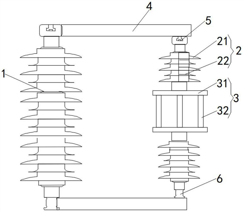
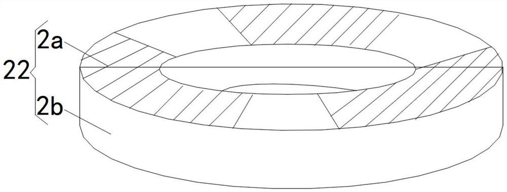
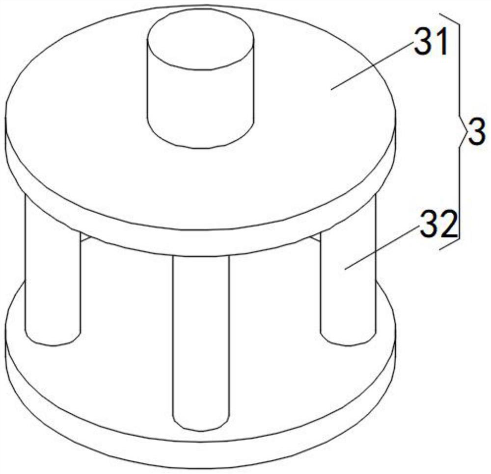
[0028] like figure 1 , figure 2 and image 3 As shown in the figure, a lightning overvoltage protection device suitable for collecting line insulators in a high wind speed environment includes an insulator 1. Both conductive ends of the insulator 1 are provided with a voltage limiting mechanism 2, and the voltage limiting mechanism 2 on both sides forms a parallel connection with the insulator 1. structure, a wind-proof and anti-bending mechanism 3 is arranged between the voltage limiting mechanisms 2 on both sides;
[0029] Further, the two voltage-limiting mechanisms 2 are symmetrically arranged at both ends of the wind-proof and anti-bending mechanism 3, which are symmetrically designed in form and beautiful in appearance. Mechanism 3 is balanced under the action of external force, improving stability;
[0030] The voltage limiting mechanism 2 includes a silicone rubber shed 21 and a plurality of stacked annular resistor sheets 22. The annular resistor sheet 22 is made ...
Embodiment 2
[0035] like figure 1 and image 3 As shown, the windproof and anti-bending mechanism 3 includes a connecting plate 31 and a support rod 32, a connecting plate 31 is provided on one end of the voltage limiting mechanism 2 on both sides, and a support rod 32 is arranged between the connecting plates 31 on both sides;
[0036] The radius of the connecting plate 31 is between 25-35cm, and the height of the support rod 32 is between 35-45cm;
[0037] The number of the support rods 32 is four, and the four support rods 32 between the connecting plates 31 on both sides form a cube-shaped structure. It is a square-shaped support structure composed of epoxy resin material, which has high flexural strength and is suitable for high wind speed environments, and the windproof and anti-bending mechanism 3 composed of epoxy resin material is molded at one time, which is conducive to modular production. The investment cost is reduced, and the maintenance is free in the later period.
Embodiment 3
[0039] like figure 1 As shown, it also includes a conductive member 4, a first connecting member 5 and a second connecting member 6. The two ends of the insulator 1 and the opposite ends of the voltage limiting mechanism 2 on both sides are respectively provided with a first connecting member 5 and a second connecting member. 6, the first connecting piece 5 and the second connecting piece 6 on the same side are respectively connected with the adjacent conductive pieces 4;
[0040] Among them, the conductive member 4 is a cross arm angle steel, the first connecting member 5 is a cap socket, and the second connecting member 6 is a ball head. The ball head constitutes the connection between the insulator 1 , the voltage limiting mechanism 2 and the conductive member 4 , and the other end of the voltage limiting mechanism 2 is connected to the grounding with the external installation components through the cross arm angle steel.
[0041] Working principle: Under normal conditions...
PUM
| Property | Measurement | Unit |
|---|---|---|
| thickness | aaaaa | aaaaa |
| radius | aaaaa | aaaaa |
| height | aaaaa | aaaaa |
Abstract
Description
Claims
Application Information
 - R&D
- Intellectual Property
- Life Sciences
- Materials
- Tech Scout
- Unparalleled Data Quality
- Higher Quality Content
- 60% Fewer Hallucinations
Browse by: Latest US Patents, China's latest patents, Technical Efficacy Thesaurus, Application Domain, Technology Topic, Popular Technical Reports.
© 2025 PatSnap. All rights reserved.Legal|Privacy policy|Modern Slavery Act Transparency Statement|Sitemap|About US| Contact US: help@patsnap.com


